


Workman HD SeriesPage 9 − 12Hydraulic System
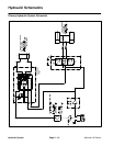
Hydraulic Circuit Operation
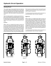
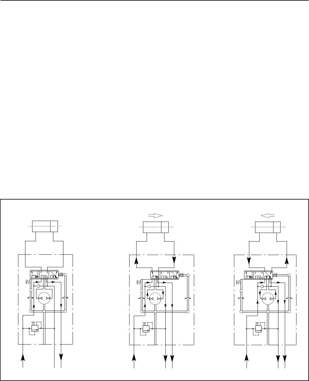
Steering Circuit
The hydraulic gear pump supplies flow for the steering
circuit and for raising and lowering the bed. Pump output
flows to the steering control valve before reaching the lift
valve so the steering circuit has priority. Circuit pressure
is limited by a relief valve located in the steering control
valve.
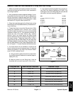
When the steering wheel is not being turned with the en-
gine running (hydraulic pump being rotated), flow enters
the steering control valve at the P port and by−passes
the rotary meter and steering cylinder. Flow leaves the
control valve through the E port and is directed to the lift
valve.
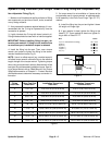
Left Turn
When a left turn is made with the engine running, the
turning of the steering wheel positions the spool valve so
that flow goes through the top of the spool. Flow entering
the steering control valve at the P port passes through
the rotary meter and is directed out the L port. Pressure
contracts the steering cylinder for a left turn. The rotary
meter ensures that the oil flow to the cylinder is propor-
tional to the amount of the turning on the steering wheel.
Fluid leaving the steering cylinder flows back through
the spool valve, then out the T port and returns to the hy-
draulic reservoir (transaxle).
The steering wheel and steering control valve return to
the neutral position when turning is completed.
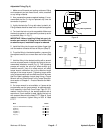
Right Turn
When a right turn is made with the engine running, the
turning of the steering wheel positions the spool valve so
that flow goes through the bottom of the spool. Flow en-
tering the steering control valve at the P port passes
through the rotary meter and is directed out port R. Pres-
sure extends the steering cylinder for a right turn. The
rotary meter ensures that the oil flow to the cylinder is
proportional to the amount of the turning on the steering
wheel. Fluid leaving the cylinder flows back through the
spool valve, then out the T port and to the hydraulic res-
ervoir (transaxle).
The steering wheel and steering control valve return to
the neutral position when turning is completed.
P
T
E
L
R
STEERING CYLINDER
STEERING
CONTROL
PISTON MOVEMENT
P
T
E
L
R
1800 to 1900
PSI
STEERING CYLINDER
NO PISTON MOVEMENT
NEUTRAL POSITION LEFT TURN
P
T
E
L
R
STEERING CYLINDER
PISTON MOVEMENT
RIGHT TURN
VALVE
STEERING
CONTROL
VALVE
STEERING
CONTROL
VALVE
1800 to 1900
PSI
1800 to 1900
PSI
Figure 13