


Workman HD SeriesPage 9 − 50Hydraulic System
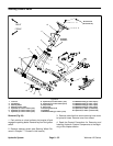
Lift Valve Service
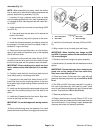
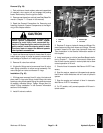
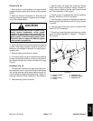
Disassembly (Fig. 38)
1. After removing lift valve from vehicle, wash valve in
solvent and dry thoroughly.
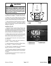
2. Carefully mount lift valve in a vise so that mounting
pads are against jaws of vise. Lift valve spool retaining
ring should be facing up.
3. Remove two (2) hex cap plugs from side of valve
body. Inside valve body, behind each hex cap plug, there
is a spring, ball and cam pin; remove these parts.
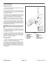
NOTE: Remove check ball seats only if they need re-
placement; the seats are press fit into the valve body.
4. Remove retaining ring from spool. Remove spool re-
taining ring, spring retainer, spacer, spring and second
spool retaining ring. Carefully push and twist spool to re-
move spool from valve body.
IMPORTANT: When removing O−rings from valve
body, be very careful to not scratch valve bore fin-
ish.
5. Use a hooked scribe or thin screwdriver to remove
O−rings from inside bore of valve body. These O−rings
are the seals for the spool.
6. Inspect all components for wear, paying special
attention to the spool. Signs of wear on one side of the
spool may indicate a bent spool. Inspect the spool for
flatness and replace if necessary.
Assembly (Fig. 38)
1. Clean all components thoroughly before assembly.
Use new O−rings when assembling lift valve.
2. Coat all O−rings and spool with clean Dexron III ATF
before installation into valve body. Assemble compo-
nents in reverse order of disassembly. Install spool into
valve body before inserting cam pins, balls, springs and
hex cap plugs.
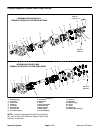
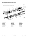
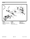
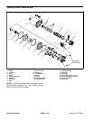
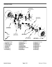
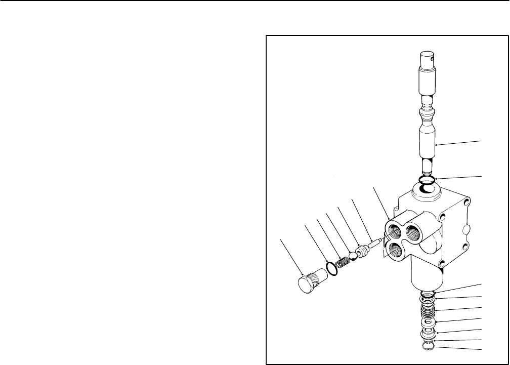
1. Hex cap plug (2)
2. O−ring (2)
3. Spring (2)
4. Check ball (2)
5. Check ball seat (2)
6. Cam pin (2)
7. Valve body
8. Spool
9. O−ring
10. Spring retainer
11. Spring
12. Spacer
13. Spool retaining ring
14. Retaining ring
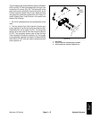
Figure 38
1
2
3
4
5
6
7
8
9
10
11
12
13
14
10
9