


Workman HD SeriesPage 6 − 18Drive Train
16.Put blocking under engine for support. Support trans-
axle with a floor jack or suspend transaxle from vehicle
frame rails.
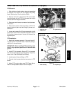
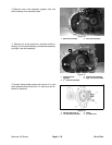
17.Remove isolation mount assemblies and transaxle
mounts (Fig. 16).
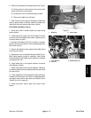
18.Remove driveshaft clamp bolts, then slide transaxle
side−to−side to disconnect each driveshaft from axle
shafts on transaxle.
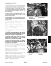
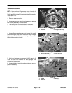
19.Remove cap screws securing clutch bell housing to
engine. Note location of washers and harness brackets.
20.Carefully pull transaxle back to disengage transaxle
input shaft from clutch. Use floor jack to lower transaxle
and slide out rear of vehicle under the frame.
21.Note location and retrieve two (2) dowel pins from
bell housing.
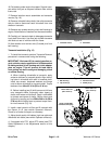
Transaxle Installation (Fig. 12)
1. To install the transaxle, perform Transaxle Removal
procedure in reverse order noting the following:
IMPORTANT: Workman HD (air cooled, gasoline en-
gine) vehicles require application of silicone sealant
to mating surface of bell housing and clutch adapter
plate on engine. This will prevent dirt and debris
from getting into bell housing and damaging clutch
or release bearing.
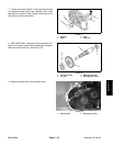
A. When installing driveshafts to transaxle, apply
antiseize lubricant to transaxle shafts. Align mount-
ing holes in driveshaft with relief in transaxle shaft.
Install cap screws, hardened washers and flange
nuts to secure driveshaft to transaxle shaft. Torque
fasteners from 40 to 45 ft−lb (55 to 61 N−m).
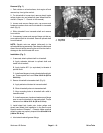
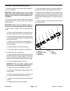
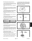
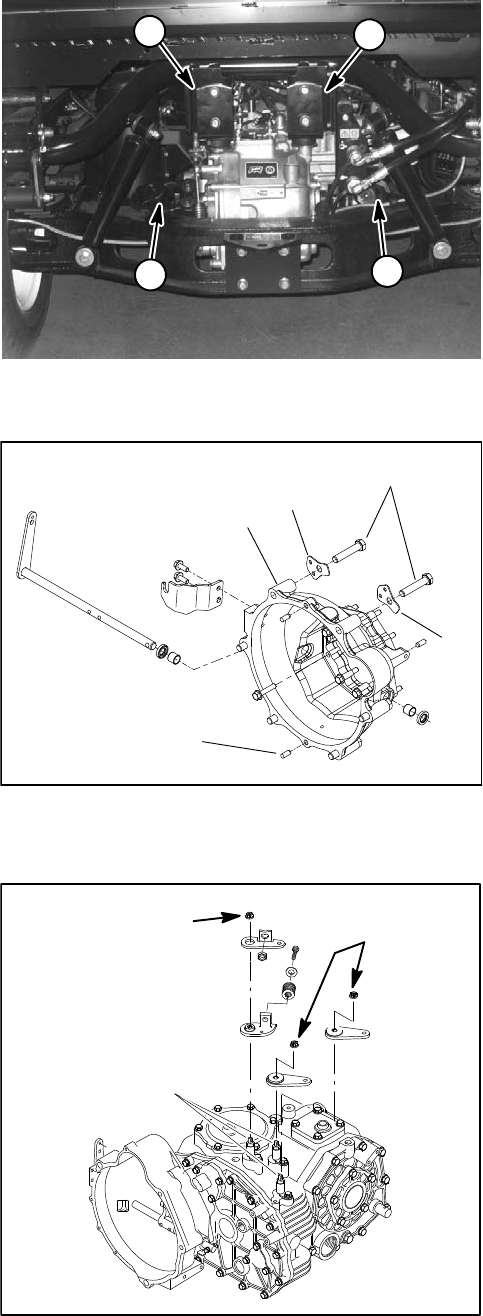
B. Before installing two (2) shift levers and shift arm
onto transaxle shafts, thoroughly clean tapers of
shafts, shift levers and shift arm. Apply Loctite #680
to threads and tapers of shafts. Secure levers and
shift arm by torquing nut from 230 to 240 in−lb (26 to
27 N−m) while holding lever to prevent torque trans-
fer into transaxle (Fig. 18).
2. Install a new hydraulic oil filter and fill transaxle with
the Dexron III oil (see vehicle Operator’s Manual).
Check for oil leaks and repair as necessary.
3. Adjust clutch pedal, shift cables, high−low cable and
differential lock cable (see vehicle Operator’s Manual).
4. If equipped with PTO, adjust PTO cable (see PTO
Cable Adjustment in the Adjustments section of this
chapter).
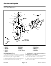
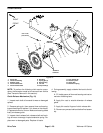
1. Transaxle mount
2. Driveshaft
Figure 16
1
2
2
1
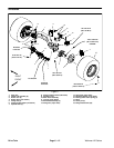
1. Bell housing
2. Cap screw (6)
3. Harness bracket
4. Dowel pin (2)
Figure 17
1
4
3
2
3
Apply Loctite #680
to threads and tapers
230 to 240 in−lb
(26 to 27 N−m)
230 to 240 in−lb
(26 to 27 N−m)
Figure 18