


Workman HD SeriesPage 8 − 30Electrical System
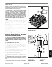
Hydraulic Solenoid Valve Coil (High Flow Hydraulics Kit)
Vehicles equipped with the High Flow Hydraulics Kit use
a hydraulic solenoid valve coil for system control (Fig.
44). When the solenoid coil is energized, hydraulic valve
shift occurs to provide hydraulic flow for the attachment.
Testing of the coil can be done with the coil installed on
the hydraulic manifold.
Testing
1. Park machine on a level surface, raise bed, stop en-
gine, apply parking brake and remove key from ignition
switch.
2. Install bed support on bed lift cylinder to prevent bed
from lowering.
3. Disconnect wire harness connector from hydraulic
solenoid valve coil.
NOTE: Prior to taking small resistance readings with a
digital multimeter, short the meter test leads together.
The meter may display a small resistance value (usually
0.5 ohms or less). This resistance is due to the internal
resistance of the meter and test leads. Subtract this val-
ue from from the measured value of the component you
are testing.
4. Using a multimeter (ohms setting), measure resis-
tance between the two connector terminals on the sole-
noid coil. The resistance for the coil should be
approximately 7.1 ohms at 68F (20C).
5. After testing is complete, connect wire harness con-
nector to the solenoid coil.
6. Remove bed support from lift cylinder and lower bed.
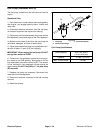
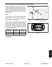
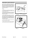
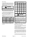
Solenoid Coil Replacement
1. Remove nut that secures solenoid coil to cartridge
valve.
2. Carefully slide coil from valve.
3. When installing coil on cartridge valve, torque nut to
5 ft−lb (6.8 N−m).
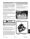
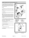
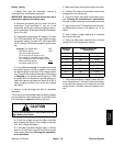
1. Hydraulic manifold
2. Hydraulic tee fitting
3. Flange head screw
4. Flange nut
5. Frame bracket
6. Hydraulic hose
7. O−ring
8. Hydraulic tube
9. O−ring
10. Hydraulic hose
11. Hydraulic tube
Figure 44
FRONT
RIGHT
3
5
2
1
4
2
6
7
7
8
9
10
9
11
1. Nut
2. Solenoid coil
3. Manifold body
Figure 45
1
2
3
5 ft−lb
(6.8 N−m)