


Workman HDX Page 3 − 9 Kubota EFI Gasoline Engine
Removal
1. Park vehicle on a level surface and engage parking
brake. Stop the engine and remove key from ignition
switch. Allow engine to cool.
2. Raise or remove the bed or other attachment(s). If
bed is raised, place safety support on lift cylinder.
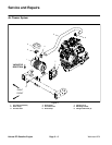
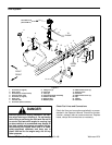
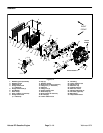
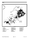
3. Note position of exhaust system heat shields and
mounting brackets before removal. Remove exhaust
system components as needed (Fig. 7).
4. Discard gaskets and thoroughly clean flange sur-
faces of exhaust tube, catalytic converter and muffler.
Installation
1. Replace any removed gaskets.
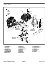
2. Fit all exhaust components to vehicle before tighten-
ing any fasteners (Fig. 7). When securing exhaust, tight-
en fasteners in the following order:
A. Hex nuts that secure exhaust tube to engine.
Torque from 22−26 ft−lbs (30 to 35 N−m).
B. Hex nuts that secure catalytic converter to ex-
haust tube. Torque from 22−26 ft−lbs (30 to 35
N−m).
C. Flange head screws and flange nuts that secure
muffler to catalytic converter. Torque from 22−26 ft−
lbs (30 to 35 N−m).
D. Flange head screw that secures muffler to trans-
axle.
E. Flange head screws and flange nuts that secure
muffler to shift cable mount bracket.
F. Carriage bolts and flange nuts that secure muffler
to mount plate.
3. Install all exhaust system heat shields.
NOTE: If oxygen sensor was removed, torque sensor
from 28 to 36 ft−lb (38 to 49 N−m).
4. Lower or install bed or attachment(s).
Kubuta EFI
Gasoline Engine