


Workman HD Series Page 7 - 25 Chassis
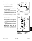
Disassembly (Fig. 16)
1. Park vehicle on a level surface, shut engine off, re-
move key from ignition switch and apply parking brake.
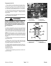
2. To remove tie rod from vehicle (Fig. 17):
A. Remove cotter pinand slotted hex nut that secure
outer tie rod ball joint stud to knuckle.
B. Use puller to separate ball joint from knuckle.
C. Unscrew inner tie rod end from center link and re-
move tie rod from vehicle.
D. If necessary, loosen jam nut and remove outer tie
rod end from inner tie rod. Count the number of revo-
lutions it takes to remove outer rod end so new rod
end can be installed without changing the wheel
alignment.
3. To remove steering linkage and center link assembly
from vehicle:
A. Remove tie rods from center link (see above).
B. Remove seat base from vehicle ( see Seat Base
Removal in this section).
C. Remove cotter pin andslotted hexnut that secure
steering cylinder ball joint to steering linkage. Sepa-
rate steering cylinder from steering linkage.
D. Remove fasteners that secure steering linkage
and center link assembly to frame. Remove assem-
bly from frame.
E. Disassemble steering linkage and center link as-
sembly as required.
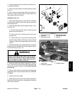
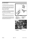
IMPORTANT: Spindle nuts are staked (de -
formed) to the idler arm and pitman arm during
assembly. Clear away the deformed area of the
nut before removing the nutfrom thearm ordam-
age to the arm threads will occur.
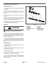
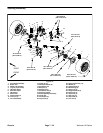
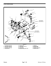
Figure 17
1. Center link
2. Inner tie rod end
3. Jam nut
4. Outer tie rod end
5. Knuckle (LH shown)
6. Cotter pin
7. Slotted hex nut
5
3
2
1
4
6
35 to 40 ft- lb
(48 to 55 N- m)
70 to 80 ft- lb
(94 to 109 N-m)
45 to 55 ft- lb
(61to74N-m)
Loctite #271
FRONT
RIGHT
7
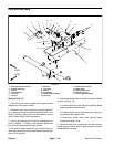
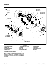
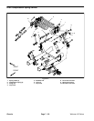
Figure 18
1. Pivot mount
2. Flange bushing (2)
3. Flange bushing (2)
4. Wave washer (2)
5. Thrust washer (2)
6. Pitman arm
7. Idler arm
8. Spindle nut (2)
2
4
1
3
5
6
7
8
85 ft- lb
(115 N- m)
FRONT
RIGHT
STEERING
LINKAGE
ASSEMBLY
STAKED
Chassis