


Workman HD SeriesPage 8 − 12Electrical System
Clutch Switch(s)
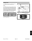
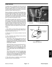
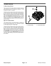
A proximity switch is attached to the frame under the
dash of all units (Fig. 12). The switch is in its normal open
position as long as the clutch pedal is released (clutch
engaged). When the clutch pedal is depressed (clutch
disengaged), the pedal is positioned close to the clutch
switch causing the switch to close. The closed clutch
switch is used in the starting interlock system to make
sure that the drive system is disengaged during engine
starting.
An additional switch is attached to the frame under the
dash of 4WD units only (Fig. 12). The terminals of this
switch are closed when the clutch pedal is released
(clutch engaged − clutch pedal depressing switch plun-
ger). In this position current is allowed to pass through
the switch to energize the 4WD relay. When the clutch
pedal is depressed (clutch disengaged − clutch pedal
not contacting the switch plunger) the terminals switch
to the normally open state, and the current path to the re-
lay is broken.
Testing
1. Park vehicle on a level surface, shut engine off, re-
move key from ignition switch and apply parking brake.
Locate the clutch switch (Fig. 12).
2. Remove hood (see Hood Removal in Chapter 7 −
Chassis).
3. Use a multimeter (ohms setting) to test continuity
across the switch terminals.
All Units: Disconnect the wire harness connector
from clutch proximity switch. Check continuity
across the two (2) switch terminals. There should
be continuity (zero ohms) when the clutch pedal is
depressed and there should not be continuity (infi-
nite ohms) when the clutch pedal is released.
4WD Units: Disconnect the wire harness connector
from clutch switch. Check continuity across the two
(2) switch terminals. There should not be continuity
(infinite ohms) when the clutch pedal is depressed
and there should be continuity (zero ohms) when
the clutch pedal is released.
4. After switch testing is completed, connect the wire
harness connector(s) to the switch(s).
5. Install hood (see Hood Installation in Chapter 7 −
Chassis).
Figure 12
1. Clutch pedal
2. Clutch proximity switch
(all units)
3. Clutch switch
(4WD units only)
1
3
2