


Workman HD SeriesPage 8 − 22Electrical System
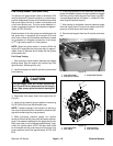
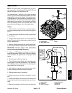
Fuel Gauge Sender (Workman HD & HDX−D)
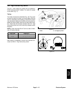
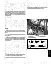
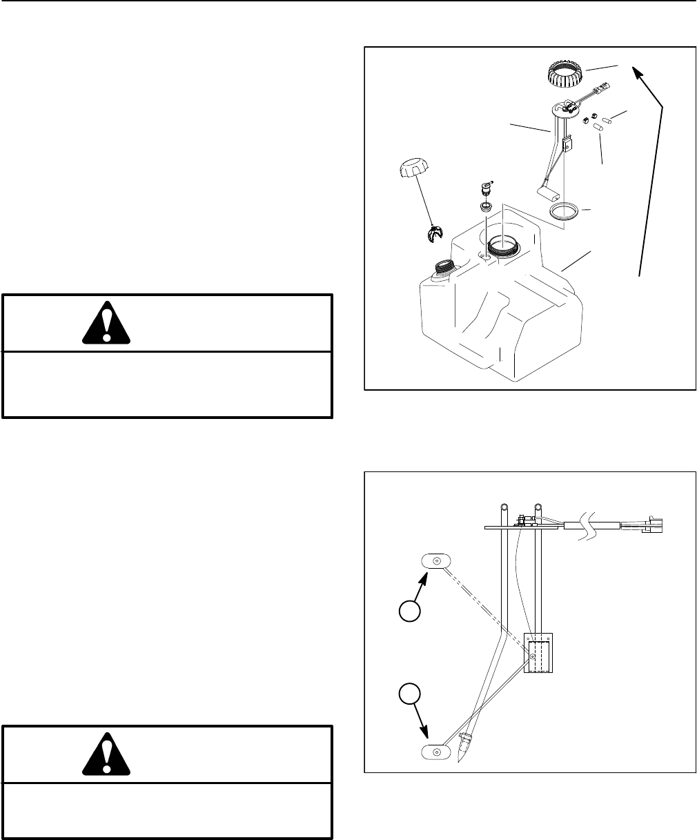
The fuel gauge sender is located in the fuel tank (Fig.
30). The fuel gauge sender on Workman HDX vehicles
(Kubota EFI gasoline engine) is included with the fuel
pump and fuel filter assembly that fits into the fuel tank.
Use the following procedure to test either style sender.
Testing
1. Park machine on a level surface, raise bed, stop en-
gine, apply parking brake and remove key from ignition
switch. Install bed support on bed lift cylinder to prevent
bed from lowering.
2. Disconnect the wire harness connector (white and
black wires) from the fuel sender.
CAUTION
When testing circuit wiring and fuel gauge, make
sure wire connections are secure before turning
ignition switch to ON to prevent an explosion or
fire from sparks.
3. To test the circuit wiring and fuel gauge, use a jumper
wire to connect the two (2) terminals in the wire harness
connector. Make sure that jumper wire connections are
secure. Turn ignition switch to ON. Fuel gauge should in-
dicate a full fuel tank. Turn ignition switch OFF and con-
tinue testing fuel sender if circuit wiring and gauge are
acceptable.
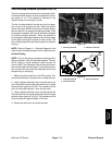
4. Remove fuel hoses from fuel sender fittings. Remove
fuel sender cap that secures the sender in the fuel tank.
NOTE: Do not allow fuel sender assembly to rotate dur-
ing removal or damage to the sender float arm may res-
ult.
5. Remove sender and gasket from the fuel tank. Clean
all fuel from the sender.
CAUTION
Make sure sending unit is completely dry (no fuel
on it) before testing. Perform test away from the
tank to prevent an explosion or fire from sparks.
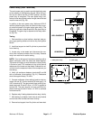
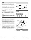
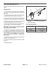
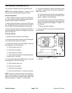
6. Check resistance of the sender with a multimeter.
A. Resistance with the float in the full position (com-
pletely up) should be from 5 to 8 ohms.
B. Resistance with the float in the empty position
(completely down) should be from 89 to 95 ohms.
1
2
3
6
4
5
Figure 30
1. Fuel gauge sender
2. Fuel sender cap
3. Gasket
4. Fuel hose (from engine
)
5. Fuel hose (to pump)
6. Fuel tank
FUEL SENDER FROM
WORKMAN HD & HDX−D
SHOWN
175 to 200 in−lb
(20 to 22 N−m)
Figure 31
1
2
1. Sender full position 2. Sender empty position
FUEL SENDER FROM
WORKMAN HD & HDX−D
SHOWN
7. Replace fuel gauge sender if necessary.
8. After testing, install sender into fuel tank and secure
with gasket and fuel sender cap. Secure fuel hoses to fit-
tings on sender and connect fuel sender connector to
wire harness.
9. Remove bed support from bed lift cylinder and lower
bed.