


Workman HD Series Page 6 − 15 Drive Train
Power−Take−Off (PTO) Removal & Installation (If Equipped)
PTO Removal
1. Park vehicle on a level surface, raise and support bed
(if installed), shut engine off and engage the parking
brake. Remove key from the ignition switch.
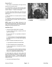
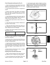
2. Remove clevis pin to disconnect PTO control cable
clevis from lever arm on PTO. Do not loosen jam nuts to
remove cable from support bracket.
3. Disconnect wire harness connector that attaches to
PTO switch.
4. Disconnect hydraulic hose from fitting on PTO. Put
caps or plugs on open hose and fitting to prevent con-
tamination.
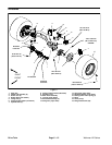
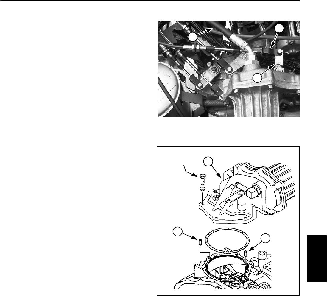
5. Loosen and remove five (5) cap screws and nut with
washer that secure PTO to transaxle. Separate PTO and
O−ring from transaxle case. Locate and remove two
alignment pins.
PTO Installation
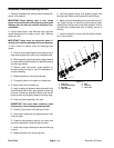
1. Apply multi−purpose grease to O−ring and insert O−
ring into groove of transaxle case. Insert two (2) align-
ment pins in transaxle case.
IMPORTANT: When installing PTO assembly, make
sure O−ring is properly positioned in transaxle case
groove.
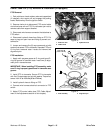
2. Install PTO to transaxle. Secure PTO to transaxle
with five (5) cap screws and nut with washer. Torque fas-
teners from 11 to 13 ft−lb (15 to 17 N−m).
3. Install hydraulic hose to fitting on PTO.
4. Connect wire harness electrical connector to PTO
switch.
5. Adjust PTO control cable (see PTO Cable Adjust-
ment in the Adjustments section of this chapter).
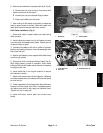
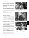
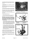
1. PTO lever arm
2. Cable clevis
3. Hydraulic hose
Figure 10
1
2
3
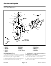
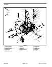
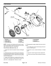
1. PTO assembly 2. Alignment pin
Figure 11
11 to 13 ft−lb
(15 to 17 N−m)
1
2
2
Drive Train