


Workman HD SeriesPage 9 − 44Hydraulic System
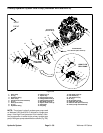
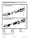
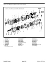
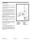
Assembly (Fig. 31)
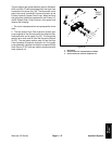
NOTE: When assembling the pump, check the marker
line on each part to make sure the pump components are
properly aligned during assembly (Fig. 32).
1. Lubricate O−rings, pressure seals, back−up seals
and thrust plate grooves with a thin coat of petroleum jel-
ly. Lubricate all other internal parts freely with clean Dex-
ron III ATF.
2. Install new seal into front cover and rear flange (HDX
and HDX−D):
A. Press shaft seal into seal bore until it reaches the
bottom of the bore.
B. Install retaining ring into the groove of the cover.
3. Install the lubricated pressure and backup seals into
the grooves in the front and rear thrust plates. Install lu-
bricated O−rings to the body.
4. Place front cover, seal side down, on a flat surface.
Apply a light coating of petroleum jelly to the exposed
side of the front cover.
5. Lubricate the drive shaft with clean Dexron III ATF.
Carefully insert the drive end of the drive shaft through
the front thrust plate with the pressure seal side down.
IMPORTANT: When installing drive shaft into front
cover, make sure that shaft seal (item 2) is not dam-
aged.
6. Carefully install shaft with front thrust plate into front
cover taking care to not damage shaft seal.
7. Lubricate the idler shaft with clean Dexron III ATF.
Install idler shaft into the remaining position in the front
thrust plate. Apply a light coating of clean hydraulic oil to
gear faces.
8. Install rear thrust plate with pressure seal side up and
open side of the seals pointing to the inlet side of the
pump.
9. Install two (2) dowel pins into front cover. Align mark-
er line on the body and front cover.
IMPORTANT: Do not dislodge seals during installa-
tion.
10.Gently slide the body onto the assembly. Firm hand
pressure should be sufficient to engage the dowel pins.
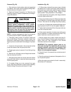
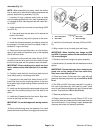
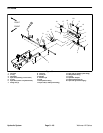
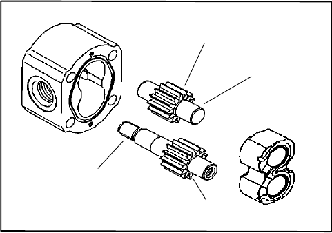
1. Gear shaft spline
2. Gear shaft
3. Gear teeth
4. Gear face edge
Figure 33
3
4
1
2
11. Install two (2) dowel pins into body (HDX and HDX−
D).
12.Align marker line on the body and rear flange.
IMPORTANT: When installing rear flange on HDX
and HDX−D pumps, make sure that shaft seal (item
18) is not damaged.
13.Carefully install rear flange onto pump assembly.
14.Install the four (4) screws with lock washers and hand
tighten.
IMPORTANT: Prevent damage when clamping the
pump into a vise; clamp on the front cover only.
Also, use a vise with soft jaws.
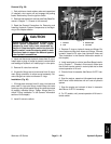
15.Place front cover of the pump into a vise with soft
jaws and alternately torque the cap screws 220 in−lb (25
N−m).
16.On HDX and HDX−D pumps, lubricate O−ring with a
thin coat of petroleum jelly and install on cover. Install
cover to rear flange and secure with two (2) socket head
screws. Torque screws 130 in−lb (15 N−m).
17.Remove pump from vise.
18.Place a small amount of clean Dexron III ATF in the
inlet of the pump and rotate the drive shaft away from the
inlet one revolution. If any binding is noted, disassemble
the pump and check for assembly problems.