


Workman HD Series Page 8 − 29 Electrical System
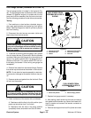
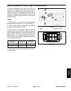
High Flow Hydraulics Kit Switch (High Flow Hydraulics Kit)
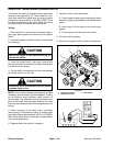
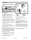
On vehicles equipped with the high flow hydraulics kit,
the switch to engage the high flow hydraulic circuit is
mounted on the dash (Fig. 42). When the high flow hy-
draulics kit switch is ON, the solenoid coil on the control
manifold is energized to allow hydraulic flow to the at-
tachment. An indicator light on the switch identifies when
the switch is ON.
Testing
1. Park machine on a level surface, stop engine, apply
parking brake and remove key from ignition switch.
2. Locate switch on dash and disconnect wire harness
electrical connector from the switch.
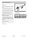
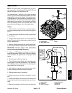
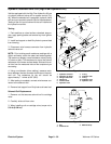
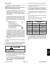
3. With the use of a multimeter (ohms setting), the
switch functions may be tested to determine whether
continuity exists between the various terminals for each
switch position. The switch terminals are marked as
shown (Fig. 43). The circuitry of this switch is shown in
the chart below. Verify continuity between switch termi-
nals for each switch position.
SWITCH
POSITION
NORMAL
CIRCUITS
OTHER
CIRCUITS
ON 2 + 3 5 + 6
OFF 2 + 1 5 + 4
4. After testing, connect wire harness electrical connec-
tor to the switch.
1. Dash 2. High flow switch
Figure 42
1
2
Figure 43
BACK OF SWITCH
Electrical
System