


4-5
Cisco CRS Carrier Routing System 8-Slot Line Card Chassis Installation Guide
OL-6256-17
Chapter 4 Installing and Removing Line Cards, PLIMs, and Associated Components
Information About Installing and Removing Cards and Associated Components
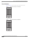
Recommended Order of Card Installation
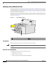
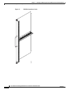
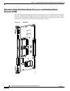
Card should be installed in a particular order. We recommend the following order when removing the
impedance carriers and installing the cards in the chassis (see Figure 4-3 and Figure 4-4):
1. Install the RP cards first one card at a time, the left one (slot RP0) before the right one (slot RP1).
Tighten the screws only after fully inserting both RP cards.
Note It is important to engage and partially tighten all screws first, before fully tightening them with
a screwdriver. This action helps ensure that all parts are aligned properly in the chassis.
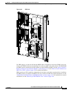
2. Install the switch fabric cards one at a time in the same manner.
We recommend that you install fabric cards from left to right, starting from top to bottom, in this
order:
–
Slot SM0
–
Slot SM1
–
Slot SM2
–
Slot SM3
3. For the line cards and PLIMs, you must remove one impedance carrier, install a functional board,
and tighten the screw; then repeat the process until all cards and PLIMs have been installed.
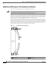
Cautions and Recommendations
Caution When you remove a card, always use the ejector levers to ensure that the connector pins disconnect from
the midplane in the sequence expected by the router.
Caution The router may indicate a hardware failure if you do not follow proper procedures. Remove or install
only one card at a time. Allow at least 15 seconds for the router to complete the preceding tasks before
removing or installing another card.
Do not operate the Cisco CRS 8-slot line card chassis with any slots completely empty; doing so could
lead to an airflow bypass condition that diverts airflow from slots containing heat-generating electronics,
possibly causing thermal alarms to occur at lower-than-expected ambient temperatures.
To avoid airflow bypass, all slots should be filled with their appropriate cards or impedance carriers. If
you have to replace a card, we recommend leaving the card in place in the chassis until you are ready to
install the new one.
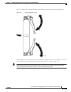
Tip To lessen the possibility of damaging the connectors on the chassis midplane, you should
visually inspect the connector pins on the cards before you insert them into the chassis.