


2-51
Cisco CRS Carrier Routing System 8-Slot Line Card Chassis Installation Guide
OL-6256-17
Chapter 2 Installing and Removing Power Components
How to Install or Remove Modular Configuration Power Components
Step 6 Remove the ESD-preventive wrist strap from the rear (MSC) side of the chassis. Go to the front of the
chassis and reattach to one of the ESD connection sockets on the front (PLIM) side of the chassis or a
bare metal surface on the chassis.
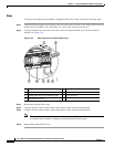
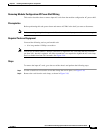
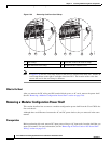
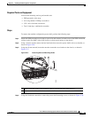
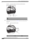
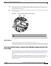
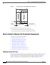
Step 7 Remove the screws, two per shelf, that secure the power shelf to the chassis. Carefully remove the power
shelf. See Figure 2-40.
Figure 2-40 Removing Screws that Secure Shelf to Chassis
What to Do Next
After performing this task, replace any front (PLIM) side cosmetic covers.
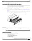
Power Up and Power Down a Chassis with a Modular Configuration AC or DC
Power Shelf
This section describes how to power up and power down a chassis with a modular configuration AC or
DC power shelf. For details on the chassis power systems, see the “Basic Chassis Power Details” section
on page 2-2, the “DC Power Systems” section on page 2-6, and the “AC Power Systems” section on
page 2-11.
Most components on the chassis, such as the PMs and fan trays, can be removed or installed in the
chassis while it is running. Although it is possible to install or remove a power shelf while the chassis is
running, it is recommended to remove power from the chassis completely, if possible, for service
protection and safety.
1 Screws that secure power shelf to chassis.
1 1
208427