


2-8
Cisco CRS Carrier Routing System 8-Slot Line Card Chassis Installation Guide
OL-6256-17
Chapter 2 Installing and Removing Power Components
Power Component Information Common to Two Types of Power System
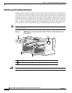
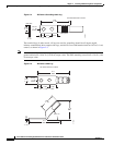
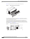
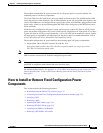
Figure 2-4 DC Power Grounding Cable Lug
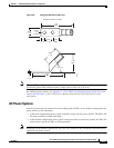
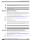
The terminal lugs (in other words, all lugs not used for grounding) should be 45-degree angled,
industry-standard dual-hole compressions lugs, and able to fit over M6 terminal studs at 0.63 in (1.6 cm)
centers, as shown in Figure 2-5.
Note In the fixed configuration power system, power cables have a 20 in.-lb (2.26 N-m) torque value and
ground cables have a 30 in.-lb (3.39 N-m) torque value. The PDU mounting screws have a 9 in.-lb (1.04
N-m) torque value.
Figure 2-5 DC Power Cable Lug
Crimp area
310354
2.40
+/- .06
0.60
+/- .04
0.10
+/- .01
0.25
+/- .04
0.380.63
+/- .02
End View
Ø 0.27
+/- .02
2 holes
All measurements in inches
310355
2.11
REF
2.11
REF
0.60
+/- .04
0.25
+/- .04
0.38
REF
0.88
+/- .04
.10
+/- .01
1.18
REF
45° +/- 5°
0.63
+/- .02
Ø 0.27
+/- .02
2 holes
All measurements in inches