


4-40
Cisco CRS Carrier Routing System 8-Slot Line Card Chassis Installation Guide
OL-6256-17
Chapter 4 Installing and Removing Line Cards, PLIMs, and Associated Components
How to Install or Remove an RP, PRP, or DRP PLIM
Required Tools and Equipment
You need the following tools and part to perform this task:
• ESD-preventive wrist strap
• Large Phillips screwdriver.
• RP, PRP, or DRP card:
–
RP card—Cisco product number: CRS-8-RP=
–
PRP card—Cisco product number: CRS-8-PRP-6G=
–
PRP card—Cisco product number: CRS-8-PRP-12G=
–
DRP card—Cisco product number: CRS-DRP-CPU=
Steps
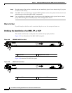
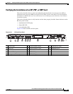
To install an RP or DRP card, follow these steps:
Step 1 Attach the ESD-preventive wrist strap to your wrist and connect its leash to an ESD connection socket
on the front (PLIM) side or a bare metal surface on the chassis.
Step 2 Remove the card from its antistatic packaging.
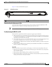
Step 3 Visually inspect the connector pins on the card before you insert it into the chassis. Do not attempt to
install a card with bent pins, as this may damage the chassis midplane connectors.
Step 4 Identify the card to be replaced in the card cage. Remove any cables connected to the front panel of the
card.
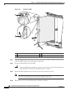
Step 5 Use the screwdriver to turn the two captive screws on the front panel of the card counterclockwise to
loosen the card from the slot.
Step 6 Grasp the two card ejector levers and simultaneously pivot both ejector levers 90 degrees away from the
front edge of the card carrier to unseat the card from the backplane connector.
Step 7 Touching only the metal card carrier, slide the card from the slot and place it directly into an antistatic
sack or other ESD-preventive container. If you plan to return the defective card to the factory, repackage
it in the shipping container you received with the replacement card.
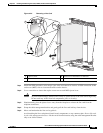
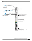
Step 8 Grasp the card carrier handle with one hand and place your other hand under the carrier to support and
guide it into the correct slot. Slide the card halfway into the slot. Avoid touching the card circuitry or
any connectors.
Note Alignment grooves exist on each slot in the card cage. When you install a card in the card cage,
make sure that you align both edges of the card carrier in the slot grooves.
Step 9 Pivot both card ejector levers so that the openings on the card ejector cams at the top and bottom of the
card pass over the tabs on each side of the card cage slot.
Caution Verify that the openings on the card ejector cams pass over the tabs; otherwise, one or both
ejector levers may bind when you attempt to close the ejector levers, thereby damaging or
breaking one or both ejector levers.