


2-45
Cisco CRS Carrier Routing System 8-Slot Line Card Chassis Installation Guide
OL-6256-17
Chapter 2 Installing and Removing Power Components
How to Install or Remove Modular Configuration Power Components
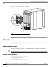
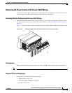
Removing AC Power Cords or DC Power Shelf Wiring
This section describes how to remove the DC input wiring, DC terminal block covers and the AC power
cords from the Cisco CRS Carrier Routing System 8-Slot line card chassis.
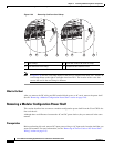
Removing Modular Configuration DC Power Shelf Wiring
This section describes how to remove the DC wiring from the modular configuration DC power shelf.
For more detailed information on chassis DC power systems, see the “DC Power Systems” section on
page 2-6.
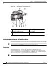
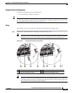
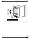
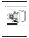
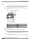
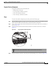
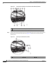
Figure 2-34 shows the power cable connections at the rear of the modular configuration DC power shelf.
Figure 2-34 Modular Configuration DC Power Shelf Power Cable Connections
Prerequisites
Before performing this task, power down and remove DC PMs in the shelf you want to disconnect.
Note Before removing wiring from the power shelf, make sure that the input power cables are not energized.
Required Tools and Equipment
You need the following tools to perform this task:
• ESD-preventive wrist strap
• 6-in. long number 1 Phillips screwdriver
• 10-mm socket wrench
281336