


2-24
Cisco CRS Carrier Routing System 8-Slot Line Card Chassis Installation Guide
OL-6256-17
Chapter 2 Installing and Removing Power Components
How to Install or Remove Fixed Configuration Power Components
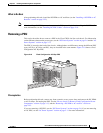
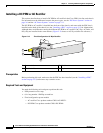
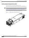
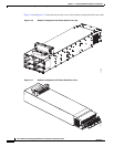
Figure 2-13 Fixed Configuration AC Wye Rectifier
Prerequisites
Before performing this task, make certain that the PDU has been installed and any cosmetic covers
removed.
Required Tools and Equipment
You need the following tools to perform this task:
• ESD-preventive wrist strap
• 6-in. long number 1 Phillips screwdriver
Steps
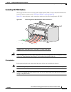
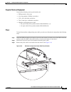
To remove a DC PEM or AC rectifier, perform the following steps:
Step 1 Attach the ESD-preventive wrist strap to your wrist and connect its leash to one of the ESD connection
sockets on the front (PLIM) side of the chassis or a bare metal surface on the chassis.
Step 2 On the front side of the chassis, pull the power tab on the bottom front of the DC PEM or AC rectifier
out to the off position.
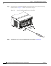
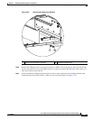
Step 3 Use the screwdriver to loosen the two captive screws on the front of the DC PEM or AC rectifier.
Step 4 Grasp the DC PEM or AC rectifier handle and pull the DC PEM or AC rectifier halfway from the bay.
Be sure to pull the module by the handle only.
Caution Take care when handling a DC PEM or AC rectifier that has been recently used—it can be hot
to the touch.
1 Power switch 3 Handle
2 Module air filter 4 Captive screws
PO
W
E
R
O
K
FL
T
A
C
F
A
IL
CB
TM
P
L
LM
O
T
122286
3
1
2
4