


2-34
Cisco CRS Carrier Routing System 8-Slot Line Card Chassis Installation Guide
OL-6256-17
Chapter 2 Installing and Removing Power Components
How to Install or Remove Modular Configuration Power Components
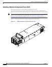
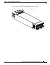
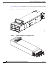
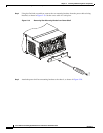
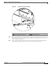
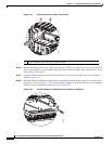
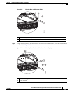
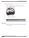
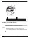
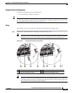
Step 12 Using the flat-blade screwdriver, install power shelf mounting screws, to secure power shelf to rear
mounting bracket. See Figure 2-25.
Figure 2-25 Securing Power Supplies to Cross Bracket and Rear Mounting Brackets
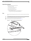
What to Do Next
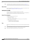
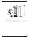
After installing the modular configuration power shelf, install the DC input wiring and DC terminal
block covers or install the AC cords, as described in “Installing AC Power Cords or DC Power Shelf
Wiring” section on page 2-35.
1 Power shelf mounting screws, two slotted screws per shelf
2 M6 hex head bolts to secure power shelf, four per shelf
208425
2 222222 2
111 1