


CHAPTER
1-1
Cisco CRS Carrier Routing System 8-Slot Line Card Chassis Installation Guide
OL-6256-17
1
Cisco CRS Carrier Routing System 8-Slot Line
Card Chassis Overview
This installation guide describes how to install the power, air circulation, line card, and external
components into and remove them from a Cisco CRS Carrier Routing System 8-Slot Line Card Chassis.
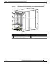
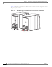
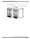
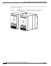
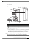
This chapter introduces the Cisco CRS 8-slot line card chassis at the highest level. It contains
illustrations of the front and rear of the chassis, complete with callouts to each hardware component. For
details on each subsystem discussed in this chapter, see Cisco CRS Carrier Routing System 8-Slot Line
Card Chassis System Description.
This chapter presents the following topics:
• Chassis Overview, page 1-1
• Chassis Components, page 1-2
• Chassis Slot Numbers, page 1-9
• Chassis Cable Management, page 1-10
• Chassis Cooling System, page 1-11
• Chassis Power System, page 1-12
• Safety Guidelines, page 1-12
• Preventing Electrostatic Discharge, page 1-13
Chassis Overview
The Cisco CRS 8-slot line card chassis can be installed in locations where the 16-slot system may not
fit (for example, colocation facilities, data centers, and many Tier II and Tier III locations). The routing
system consists of a single rack-mount chassis that contains the following major system components:
• Up to eight modular services cards (MSCs), forwarding processor (FP) cards, and label switch
processor (LSP) cards, also called line cards (up to eight)
• Physical layer interface modules, or PLIMs (up to eight, one for each line card)
• Route processor (RP) cards (up to two) or performance route processor (PRP) cards (up to two)
• Switch fabric cards (four required)
• SPA Interface Processors (SIPs) and Shared Port Adapters (SPAs) which can be installed instead of
PLIMs