


1-7
Cisco CRS Carrier Routing System 8-Slot Line Card Chassis Installation Guide
OL-6256-17
Chapter 1 Cisco CRS Carrier Routing System 8-Slot Line Card Chassis Overview
Chassis Components
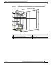
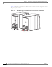
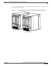
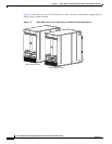
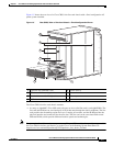
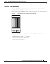
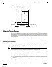
Figure 1-5 shows the rear view of a Cisco CRS 8-slot line card chassis with a fixed configuration AC
power system installed.
Figure 1-5 Rear (MSC) View of Line Card Chassis—Fixed Configuration Shown
The Cisco CRS 8-slot line card chassis contains:
• As many as eightMSC, FP or LSP cards (all types are also called line cards), and eightPLIMs. The
line card and PLIM are an associated pair of cards that mate through the chassis midplane. The line
card provides the forwarding engine for Layer 3 routing of user data, and the PLIM provides the
physical interface and connectors for the user data. The line card can be associated with several
different PLIMs, which provide different interface speeds and technologies.
Note For a complete list of line cards, route processors, SPAs and SIPs, and interface modules supported in
the Cisco CRS 8-slot line card chassis, go to the Cisco Carrier Routing System Data Sheets at:
http://www.cisco.com/en/US/products/ps5763/products_data_sheets_list.html.
1 Upper fan tray (beneath cover) 5 Lower fan tray
2 Chassis vertical mounting brackets 6 Rear exhaust screen
3 Switch fabric card (half-height) slots 7 Power system
4 MSC slots
122776
1
4
3
2
5
6
7