


2-49
Cisco CRS Carrier Routing System 8-Slot Line Card Chassis Installation Guide
OL-6256-17
Chapter 2 Installing and Removing Power Components
How to Install or Remove Modular Configuration Power Components
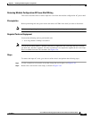
Required Tools and Equipment
You need the following tools to perform this task:
• ESD-preventive wrist strap
• 6-in. long number 1 Phillips screwdriver
• 5/32 x 6 in. flat-blade screwdriver
• Two 10-mm 6 pt. combination wrenches
Steps
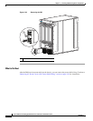
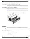
To remove the modular configuration power shelf, perform the following steps:
Step 1 Attach the ESD-preventive wrist strap to your wrist and connect its leash to one of the ESD connection
sockets on the rear (MSC) side of the chassis or a bare metal surface on the chassis.
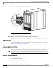
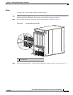
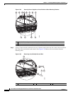
Step 2 Using a 10-mm wrench, remove the hex head bolts that secure the power shelf to the cross bracket, as
shown in Figure 2-38.
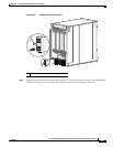
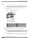
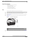
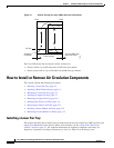
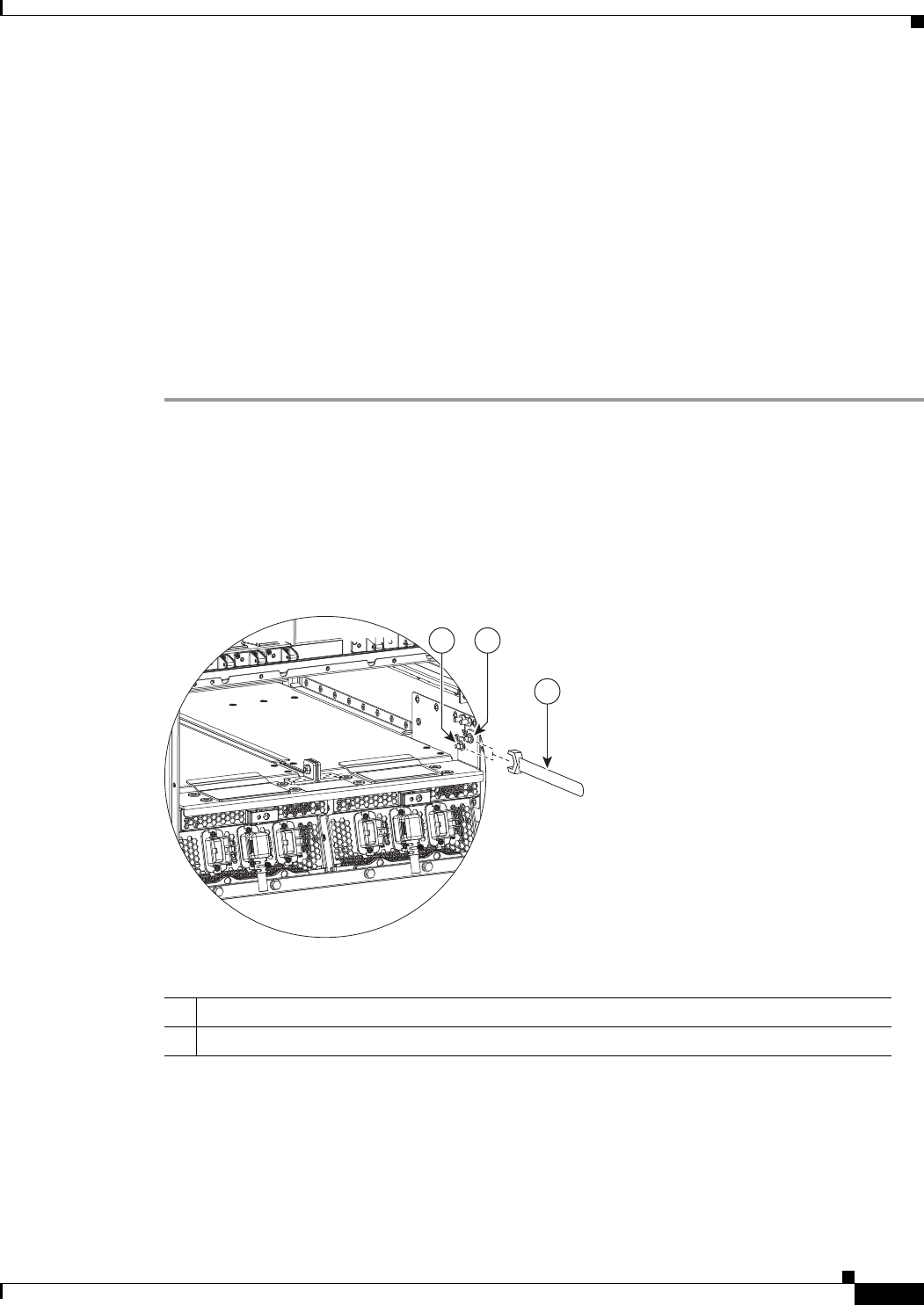
Step 3 Using the 10-mm wrench, loosen the nuts that secure the cross bracket to the chassis, as shown in
Figure 2-37.
Figure 2-37 Loosening Nuts on Mounting Studs
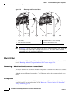
Step 4
Using the flat-blade screwdriver, remove the power shelf mounting screws, as shown in Figure 2-38.
1 M6 hex nuts that secure cross bracket to chassis (two on each side of the chassis)
2 10-mm wrench to loosen hex nuts
208426
11
2