


2-42
Cisco CRS Carrier Routing System 8-Slot Line Card Chassis Installation Guide
OL-6256-17
Chapter 2 Installing and Removing Power Components
How to Install or Remove Modular Configuration Power Components
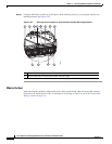
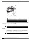
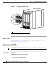
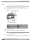
Figure 2-31 Securing the Ejector Into the PM
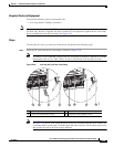
Step 4
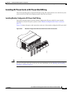
Install the second PM and fill the power shelf to the required configuration.
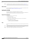
What to Do Next
After installing the PMs, you can install the cosmetic covers. For more information, see Chapter 5,
“Installing and Removing Exterior Components.”
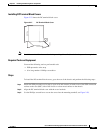
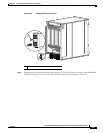
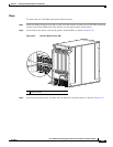
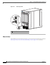
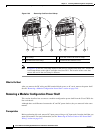
Removing AC or DC PMs
This section describes how to remove AC or DC PMs from the Cisco CRS 8-slot line card chassis.
Note Although there are differences between the AC and DC PMs, they are removed in the same manner.
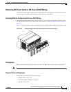
Required Tools and Equipment
You need the following tools to perform this task:
• ESD-preventive wrist strap
• 6-in. long number 1 Phillips screwdriver
1 Screw the ejector into the PM
CISCO CRS-1
S
ERI
ES
LINEC ARD CH ASS IS
254847
1