


2-19
Cisco CRS Carrier Routing System 8-Slot Line Card Chassis Installation Guide
OL-6256-17
Chapter 2 Installing and Removing Power Components
How to Install or Remove Fixed Configuration Power Components
Installing DC PDU Cables
This section describes how to wire the fixed configuration DC PDU. For more detailed information on
chassis DC power systems, see the “DC Power Systems” section on page 2-6.
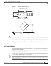
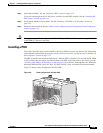
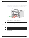
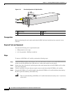
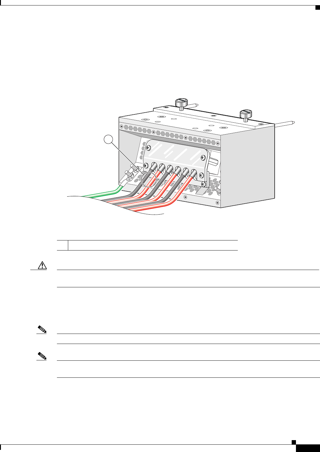
Figure 2-11 shows the power cable connections at the rear of the fixed configuration DC PDU.
Figure 2-11 Fixed Configuration DC PDU Power Cable Connections
Caution When wiring the PDU, be sure to attach the ground cable first and tighten the nuts to a torque of 30 in-lb
(3.39 N-m). When removing the wiring, be sure to remove the ground cable last.
Prerequisites
Before performing this task, ensure that both power shelves are installed in the chassis.
Note Before installing wiring on the power shelf, make sure that the input power cables are not energized.
Note If cables are wrapped with black electrical tape, be sure to remove tape from cables before installing
cabling on the power shelf.
1 Each set of cables (RTN and –48 V/–60V) is a single VDC input.
129533
1