


4-33
Cisco CRS Carrier Routing System 8-Slot Line Card Chassis Installation Guide
OL-6256-17
Chapter 4 Installing and Removing Line Cards, PLIMs, and Associated Components
How to Install or Remove an MSC, FP, or LSP
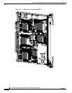
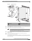
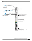
Step 5 Visually inspect the connector on the card before you insert it into the chassis. Do not attempt to install
a card with a damaged connector, as this action may damage the chassis midplane pins.
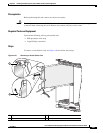
Step 6 Use both hands while inserting an line card. Use one hand on the faceplate and the other hand along the
base of the line card to guide it into a slot.
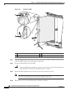
Step 7 Orient the line card so that the PCB faces left and the carrier is to the right; if the card does not slide
easily into the slot, the orientation may be wrong and the misorientation rejection flange is stopping the
card from going into the slot. Reorient the line card, if necessary.
Step 8 Make sure that the ejector levers are oriented properly to engage with the pin as the line card slides into
the slot. Carefully slide the line card into the slot until the ejector levers engage the catches, then stop.
Step 9 Simultaneously pivot the ejector levers toward the faceplate of the line card. Do not force the line card;
the ejector levers properly seat the line card against the midplane.
Note If the captive screws are difficult to tighten, check to ensure that each ejector lever is properly
secured to each catch and that the line card is properly seated in the slot.
Step 10 Partially tighten the two captive screws on the front panel of the card (either by hand or with the
screwdriver) to make sure that they are both engaged.
Step 11 Use a screwdriver to fully tighten the captive screws next to each line card ejector lever to ensure proper
EMI shielding and to prevent the card from becoming partially dislodged from the midplane.
Caution To ensure adequate space for additional PLIMs or line cards, always tighten the captive
installation screws on each newly installed PLIM before you insert another PLIM or line card.
These screws also prevent accidental removal and provide proper grounding and EMI
shielding for the system.
Step 12 Attach the bracket to the line card; use the screws that came with it.
What to Do Next
After performing this task:
• Place the impedance carrier in an antistatic bag for storage and future use.
• Replace any front cover cosmetic plates and verify that the card has been installed properly (see the
“Verifying the Installation of an MSC, FP, or LSP” section on page 4-36).
• If you are performing the initial installation of the system, install the RP cards (see the “How to
Install or Remove an RP, PRP, or DRP PLIM” section on page 4-38).
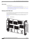
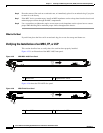
Removing an MSC, FP, or LSP
This section describes how to remove a line card from the Cisco CRS 8-slot line card chassis. For more
detailed information on the line cards, see Cisco CRS Carrier Routing System 8-Slot Line Card Chassis
System Description.