


5-2
Cisco CRS Carrier Routing System 8-Slot Line Card Chassis Installation Guide
OL-6256-17
Chapter 5 Installing and Removing Exterior Components
Installing or Removing the Front Side Exterior Components
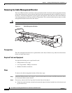
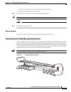
Removing the Cable Management Bracket
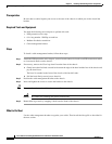
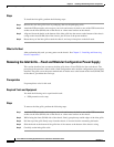
The Cisco CRS 8-slot line card chassis arrives preinstalled with a horizontal cable management bracket
on the front of the chassis and an optional horizontal cable management bracket available for the rear of
the chassis. The cable management system organizes the interface cables that enter and exit the different
cards, keeping them out of the way and free of sharp bends. This section describes how to remove a cable
management bracket from the line card chassis.
Caution Excessive bending of interface cables can damage the cables.
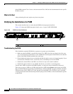
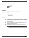
Figure 5-1 Cable Management Bracket
Prerequisites
The cable management bracket arrives preinstalled on the chassis. Remove any cables from the bracket
before you begin removing it.
Required Tools and Equipment
You need the following tools to perform this task:
• ESD-preventive wrist strap
• 6 in. long number 1 Phillips screwdriver
• Medium flat-blade screwdriver
Steps
To remove the cable management bracket, follow these steps:
Step 1 Attach the ESD-preventive wrist strap to your wrist and connect its leash to an ESD connection socket
or a bare metal surface on the chassis.
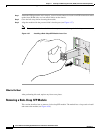
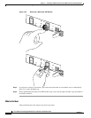
Step 2 If necessary, remove the Cisco logo bezel from the front of the chassis.
a. Gently insert the flat-blade screwdriver between the edge of the bezel and the face of the chassis and
pry the bezel loose.
122789