


2-5
Cisco CRS Carrier Routing System 8-Slot Line Card Chassis Installation Guide
OL-6256-17
Chapter 2 Installing and Removing Power Components
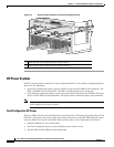
Power Component Information Common to Two Types of Power System
How to Install the Chassis Ground Cable
This section describes how to install the ground cable on the Cisco CRS 8-slot line card chassis.
Prerequisites
To connect the routing system to a network equipment building system (NEBS)-compliant bonding and
grounding system at the site, you must have the following:
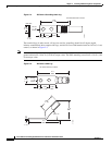
• Minimum of one grounding lug that has two M6 bolt holes with 0.63-inch (5/8 inch) (1.6 cm) of
spacing between them, center to center, and a 6-AWG multistrand copper cable. The lug is similar
to the type used for the DC-input power supply leads, as shown in Figure 2-4.
• Four M6 or equivalent hex-head nuts with integrated locking washers are shipped pre-installed on
the inside of the chassis.
• Eight M6 or equivalent hex-head bolts with integrated locking washers are shipped pre-installed on
the outside of the chassis.
• Ground cable routed upwards or downwards, per customer installation requirements. Although we
recommend at least 6-AWG multistrand copper cable, the actual cable diameter and length depend
on your router location and site environment. This cable is not available from Cisco Systems; it is
available from any commercial cable vendor. The ground cable should be sized according to local
and national installation requirements.
Caution The DC Return of the Cisco CRS 8-slot chassis should remain isolated from the system frame and
chassis (DC-I: Isolated DC Return).
Required Tools and Equipment
You need the following tools to perform this task:
• One ground lug for equipment-side ground connection. In a rack application, the rack-side of the
ground cable will also require a lug.
• Ground cable
• Crimping tool and lug specific die
• 10-mm 6 pt. combination wrench
• Torque wrench with 10-mm 6 pt. socket and rated accuracy at 30 in.-lb (3.39 N-m)
Steps
To attach the ground cable to the chassis, perform the following steps:
Step 1 Use the crimping tool mandated by the lug manufacturer to crimp the lug to the ground cable.
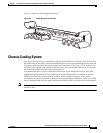
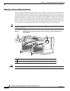
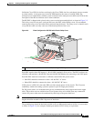
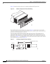
Step 2 Using the 10-mm wrench, attach the ground cable to one of the grounding points at the rear of the
chassis. Then use the torque wrench to tighten to a torque of 30 in.-lb (3.39 N-m). Figure 2-2 shows how
the ground cable is attached to the ground points on the outside of the chassis.