


2-20
Cisco CRS Carrier Routing System 8-Slot Line Card Chassis Installation Guide
OL-6256-17
Chapter 2 Installing and Removing Power Components
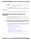
How to Install or Remove Fixed Configuration Power Components
Required Tools and Equipment
You need the following tools to perform this task:
• ESD-preventive wrist strap
• Crimping tool and lug specific die
• 3/8 in. ratchet wrench with 10-mm socket
• Torque wrench with 10-mm 6 pt. socket and rated accuracy at 30 in.-lb (3.39 N-m)
• Torque wrench with 10-mm 6 pt. socket and rated accuracy at 20 in.-lb (2.26 N-m
Steps
To wire the DC PDU, perform the following steps:
Step 1 Attach the ESD-preventive wrist strap to your wrist and connect its leash to one of the ESD connection
sockets on the rear (MSC) side of the chassis or a bare metal surface on the chassis.
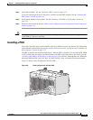
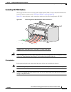
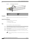
Step 2 Remove the upper plastic terminal block safety cover (leave the lower safety cover in place; as shown in
Figure 2-11). Using a standard Phillips screwdriver, remove the four screws holding the upper plastic
safety cover to the wiring terminal block.
Step 3 Use the crimping tool mandated by the lug manufacturer to crimp the lugs to the DC-input cables and
the ground cable. For details on lugs, see the “DC Power Systems” section on page 2-6.
The cable should be sized according to local and national installation requirements.
Note The terminal posts are centered 0.63 inches (5/8 inch) (1.60 cm) apart and are M6-threaded. We
recommend that you use an appropriately sized 45-degree angled industry standard 2-hole,
standard barrel compression lug.
Step 4 Using the 10-mm socket wrench, attach the ground cable to the ground cable terminal. Then use the
torque wrench to tighten to a torque of 30 in.-lb (3.39 N-m).
Step 5 Using the 10-mm socket wrench, attach the three negative cables (the red cables as shown in
Figure 2-11) and the three positive cables (the black cables as shown in Figure 2-11) to the terminal
block. Then use the torque wrench to tighten to a torque of 20 in.-lb (2.26 N-m).
Step 6 Reattach the upper plastic safety cover with a Phillips screwdriver. Insert and tighten the four screws
holding the cover to the wiring terminal block.