


2-13
Cisco CRS Carrier Routing System 8-Slot Line Card Chassis Installation Guide
OL-6256-17
Chapter 2 Installing and Removing Power Components
How to Install or Remove Fixed Configuration Power Components
The modular configuration AC power systems use A or B power shelves to provide reliable, 2N
redundant power to all chassis components.
The Cisco CRS 8-slot line card chassis does not contain an alarm module. The AC PM monitors PM
status and processes alarm functions. The AC PM distributes power and passes PM status signals to the
system. Each PM has its own integrated fuse to protect the system, and each PM is plugged into its own
power outlet. Alarms are processed through the RP. LEDs on the front panel of the RP indicate active
alarm conditions.
Unlike the fixed configuration AC power system, which requires 3-phase AC Delta or AC Wye input
power, the modular configuration AC power system requires single-phase AC input power. If you have
3-phase AC Delta or AC Wye at your equipment, a Cisco CRS PDU will be required to convert 3-phase
AC input power to single-phase AC input power for the power shelf. For further information, refer to
Cisco CRS 3-Phase AC Power Distribution Unit Installation Guide.
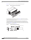
The modular configuration AC power shelf has the following input VAC power requirements:
• Single-phase, 200 to 240 VAC nominal, 50 to 60 Hz, 16 A.
Each power shelf contains three IEC-320-C22 receptacles which can accept up to three
IEC-320-C21 connector female cords.
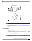
Note In order to maintain a balanced 3-phase power load, three AC PMs are required to be installed in a Cisco
CRS 8-slot line card chassis AC modular configuration power shelf.
Note If single-phase AC power is available at your site, we recommend that you use appropriate short-circuit
protection in compliance with national and local electrical codes.
For additional power details, see Appendix A, “Cisco CRS Carrier Routing System 8-Slot Line Card
Chassis Specifications” or Cisco CRS Carrier Routing System 8-Slot Line Card Chassis System
Description.
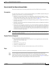
How to Install or Remove Fixed Configuration Power
Components
This section contains the following procedures:
• Before Powering the Chassis Up or Down, page 2-14
• Converting from One Fixed Configuration Power System to Another, page 2-14
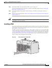
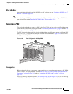
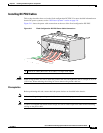
• Installing a PDU
• Removing a PDU
• Installing DC PDU Cables, page 2-19
• Removing DC PDU Wiring, page 2-21
• Installing a DC PEM or AC Rectifier
• Removing a DC PEM or AC rectifier