


2-11
Cisco CRS Carrier Routing System 8-Slot Line Card Chassis Installation Guide
OL-6256-17
Chapter 2 Installing and Removing Power Components
Power Component Information Common to Two Types of Power System
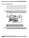
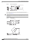
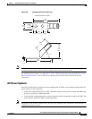
Figure 2-8 45-Degree DC Power Cable Lug
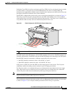
Note In the modular configuration power system, DC power cables have a torque value of 20 in.-lb (2.26 N-m)
and chassis ground cable connectors have a torque value of 30 in.-lb (3.39 N-m).
For additional power details, see Appendix A, “Cisco CRS Carrier Routing System 8-Slot Line Card
Chassis Specifications” or Cisco CRS Carrier Routing System 8-Slot Line Card Chassis System
Description.
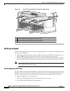
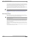
AC Power Systems
Each AC powered chassis contains two fixed configuration AC PDUs or two modular configuration AC
power shelves for 2N redundancy.
• In the fixed configuration power system, each PDU accepts one AC power rectifier. The PDUs and
AC power rectifiers are field replaceable.
• In the modular configuration power system, each power shelf can contain up to three AC PMs. The
power shelves and the AC PMs are field replaceable.
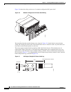
Note Depending on the hardware deployed at your site, your system may not consume the maximum power
supplied by the power system.
310355
2.11
REF
2.11
REF
0.60
+/- .04
0.25
+/- .04
0.38
REF
0.88
+/- .04
.10
+/- .01
1.18
REF
45° +/- 5°
0.63
+/- .02
Ø 0.27
+/- .02
2 holes
All measurements in inches