


2-21
Cisco CRS Carrier Routing System 8-Slot Line Card Chassis Installation Guide
OL-6256-17
Chapter 2 Installing and Removing Power Components
How to Install or Remove Fixed Configuration Power Components
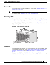
Removing DC PDU Wiring
This section describes how to remove the wiring from the fixed configuration DC PDU. For more
detailed information on chassis DC power systems, see the “DC Power Systems” section on page 2-6.
Caution When removing DC wiring from the fixed configuration DC PDU be sure to remove the ground cable
last.
Prerequisites
Before performing this task, power down and remove DC PEMs in the shelf you want to disconnect.
Note Before removing wiring from the power shelf, make sure that the power cord is not plugged into the
facility power.
Required Tools and Equipment
You need the following tools to perform this task:
• ESD-preventive wrist strap
• 3/8-in. ratchet wrench with 10-mm socket
Steps
To remove the wiring from the DC PDU, perform the following steps:
Step 1 Attach the ESD-preventive wrist strap to your wrist and connect its leash to one of the ESD connection
sockets on the rear (MSC) side of the chassis or a bare metal surface on the chassis.
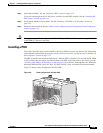
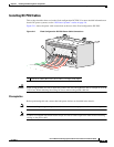
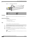
Step 2 Remove the upper plastic terminal block safety cover (leave the lower safety cover in place; as shown in
Figure 2-11). Using a standard Phillips screwdriver, remove the four screws holding the upper plastic
safety cover to the wiring terminal block.
Step 3 Using the 10-mm socket wrench, remove the three positive and three negative cables from the terminal
block.
Step 4 Using the 10-mm socket wrench, remove the ground cable from the ground cable terminal.
Note When a cable is removed from the rear of the fixed configuration DC power shelf, we
recommend that it should be wrapped with standard black electrical tape.
Step 5 Reattach the upper plastic safety cover with a Phillips screwdriver. Insert and tighten the four screws
holding the cover to the wiring terminal block.