


2-53
Cisco CRS Carrier Routing System 8-Slot Line Card Chassis Installation Guide
OL-6256-17
Chapter 2 Installing and Removing Power Components
How to Install or Remove Modular Configuration Power Components
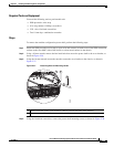
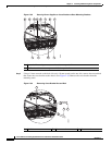
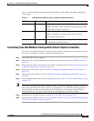
Table 2-1 shows the LED status indicator lights for the AC and DC PMs in a modular configuration
power supply.
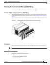
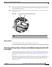
Converting from One Modular Configuration Power System to Another
To convert a Cisco CRS 8-slot line card chassis with a modular configuration power system from AC to
DC power, or from DC to AC power, perform the following steps:
Step 1 Power down the chassis completely.
Step 2 Remove the AC or DC PMs from the power shelves. See the “Removing AC or DC PMs” section on
page 2-42,
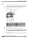
Step 3 Remove the AC or DC wiring from the rear of the power shelves. See the “Removing AC Power Cords
or DC Power Shelf Wiring” section on page 2-45.
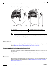
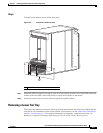
Step 4 Remove the power shelves. See the “Removing a Modular Configuration Power Shelf” section on
page 2-48.
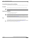
Step 5 Install the new power shelves. See the “Installing a Modular Configuration Power Shelf” section on
page 2-26.
Step 6 Install the power shelf wiring. See the “Installing AC Power Cords or DC Power Shelf Wiring” section
on page 2-35.
Note If you are converting from modular configuration DC to modular configuration AC power, and if you
have 3-phase AC Delta or AC Wye power at your equipment, a Cisco CRS PDU will be required to
convert 3-phase AC input power to single-phase AC input power for the power shelf. For further
information, refer to Cisco CRS 3-Phase AC Power Distribution Unit Installation Guide.
Step 7 Install the AC or DC PMs. See the “Installing AC or DC PMs” section on page 2-40.
Step 8 Power the chassis back up. See the “Power Up and Power Down a Chassis with a Modular Configuration
AC or DC Power Shelf” section on page 2-51.
Table 2-1 PM LED Status Indicator Lights—Modular Configuration Power
LED Name Color Function or Meaning
Input_OK Green On: The input voltage is present and within regulation range.
Blinking: The input voltage is present but out of regulation range.
Off: The input voltage is not present.
Output_OK Green On: The output voltage is on.
Blinking: The PM is in a power limit or an OC condition.
Off: The output voltage is off.
Fault Red On: An internal fault is detected within the PM.
Off: The PM has no internal fault.