


4-50
Cisco CRS Carrier Routing System 8-Slot Line Card Chassis Installation Guide
OL-6256-17
Chapter 4 Installing and Removing Line Cards, PLIMs, and Associated Components
How to Install or Remove a Physical Layer Interface Module
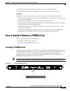
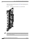
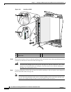
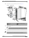
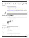
Figure 4-33 Installing a PLIM
Step 6
Pivot both card ejector levers so that the openings on the card ejector cams at the top and bottom of the
card pass over the tabs on each side of the card cage slot.
Caution Verify that the openings on the card ejector cams pass over the tabs; otherwise, one or both
ejector levers may bind when you attempt to close the ejector levers, thereby damaging or
breaking one or both ejector levers.
Step 7 Continue sliding the card into the card cage slot until the openings on the card ejector cams engage the
tabs on each side of the card cage slot.
Note Guide pins exist that make initial contact with the backplane connector as you slide a card into
its slot. After the guide pins make contact, continue pushing on the card carrier until the card
ejector levers begin pivoting forward, toward the handle in the card carrier.
1 Captive screw 3 Direction of installation or removal
2 Ejector lever
122790
3
1
2