


2-37
Cisco CRS Carrier Routing System 8-Slot Line Card Chassis Installation Guide
OL-6256-17
Chapter 2 Installing and Removing Power Components
How to Install or Remove Modular Configuration Power Components
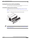
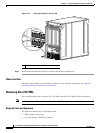
Installing DC Terminal Block Covers
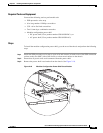
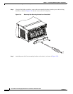
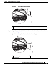
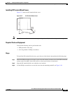
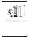
Figure 2-27 shows the DC terminal block cover.
Figure 2-27 DC Terminal Block Cover
Note Install the terminal block cover after the input wiring is installed, but before the power is energized.
Required Tools and Equipment
You need the following tools to perform this task:
• ESD-preventive wrist strap
• 6-in. long number 1 Phillips screwdriver
Steps
To install the DC terminal block covers, go to the rear of the chassis and perform the following steps:
Step 1 Attach the ESD-preventive wrist strap to your wrist and connect its leash to one of the ESD connection
sockets on the rear (MSC) side of the chassis or a bare metal surface on the chassis.
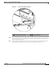
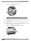
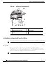
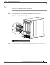
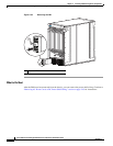
Step 2 Align the DC terminal block cover with the cover latch tab.
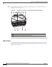
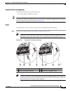
Step 3 Use the Phillips screwdriver to secure the screw into the mounting standoff, see Figure 2-28.
207816