


4-19
Cisco CRS Carrier Routing System 8-Slot Line Card Chassis Installation Guide
OL-6256-17
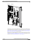
Chapter 4 Installing and Removing Line Cards, PLIMs, and Associated Components
How to Install or Remove a Pillow Block
Steps
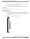
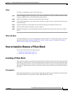
To remove an impedance carrier, follow these steps:
Step 1 Attach the ESD-preventive wrist strap to your wrist and connect its leash to an ESD connection socket
on the rear (MSC) side or a bare metal surface on the chassis.
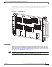
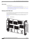
Step 2 Identify the impedance carrier to be removed from the card cage.
Step 3 To loosen the impedance carrier from the slot, turn the two captive screws on the front panel of the card
counterclockwise.
Step 4 Grasp the impedance carrier handle with one hand and gently pull it halfway from the slot.
Step 5 Place one hand under the impedance carrier to guide it.
Step 6 Holding the impedance carrier underneath and by the handle, pull it from the slot and set it carefully
aside.
What to Do Next
After performing this task, store the impedance carrier for future use. You may now install a card in the
uncovered slot. See the “Installing an MSC, FP, or LSP” section on page 4-29 and the “Installing a
PLIM” section on page 4-47 for further details.
How to Install or Remove a Pillow Block
This section contains the following procedures:
• Installing a Pillow Block, page 4-19
• Removing a Pillow Block, page 4-21
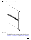
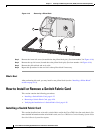
Installing a Pillow Block
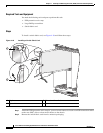
This section describes how to install a replacement pillow block on the chassis after removing a damaged
pillow block. A pillow block is a bracket with a pin that is attached to the chassis above and below each
card slot. When you install or remove a card from the chassis, the card ejector levers hook into the pillow
blocks above and below the card slot to secure the cards to the slot and allow you to install and remove
the cards.
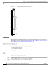
Prerequisites
Before performing this task, you must first open the front cosmetic doors (if installed). Have the pillow
block replacement kit (Cisco product number: CRS-PILLBLK=) at hand.