


2-40
Cisco CRS Carrier Routing System 8-Slot Line Card Chassis Installation Guide
OL-6256-17
Chapter 2 Installing and Removing Power Components
How to Install or Remove Modular Configuration Power Components
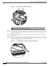
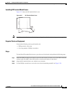
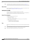
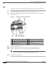
Step 2 Use the Phillips screwdriver to tighten the screw that clamps the cord in place, see Figure 2-29.
What to Do Next
After you install the DC wiring and DC terminal block covers or AC input cords, install the AC or DC
PMs, as described in “Installing AC or DC PMs” section on page 2-40.
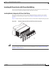
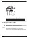
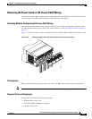
Installing AC or DC PMs
This section describes how to install modular configuration AC or DC PMs.
The modular configuration AC or DC PMs are installed into the front of the chassis. Although there are
differences between the AC and DC PMs, they are installed in the same manner.
Required Tools and Equipment
You need the following tools to perform this task:
• ESD-preventive wrist strap
• 6-in. long number 1 Phillips screwdriver
• Torque screwdriver with number 1 Phillips bit and rated accuracy at 5.5 in-lb (0.62 N-m)
• Modular configuration AC or DC PM
–
AC PM (Cisco product number CRS-PM-AC=)
–
DC PM (Cisco product number CRS-PM-DC=)
Steps
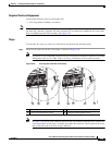
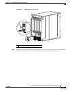
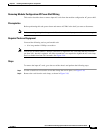
To install the AC or DC PMs in the power shelf, go to the front of the chassis and perform the following
steps:
Step 1 Attach the ESD-preventive wrist strap to your wrist and connect its leash to one of the ESD connection
sockets on the front (PLIM) side of the chassis or a bare metal surface on the chassis.
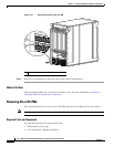
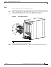
Step 2 Using two hands to support and guide the PM, slide it into the power shelf.