


4-49
Cisco CRS Carrier Routing System 8-Slot Line Card Chassis Installation Guide
OL-6256-17
Chapter 4 Installing and Removing Line Cards, PLIMs, and Associated Components
How to Install or Remove a Physical Layer Interface Module
Prerequisites
Before performing this task, remove any front cover plates.
Required Tools and Equipment
You need the following tools and part to perform this task:
• ESD-preventive wrist strap
• Medium Phillips screwdriver
• PLIM
Steps
To install a PLIM, follow these steps:
Step 1 Attach the ESD-preventive wrist strap to your wrist and connect its leash to an ESD connection socket
on the front (PLIM) side or a bare metal surface on the chassis.
Step 2 Remove the PLIM from its antistatic packaging.
Step 3 Visually inspect the connector pins on the card before you insert it into the chassis. Do not attempt to
install a card with bent pins, as this may damage the chassis midplane connectors.
Step 4 Remove the PLIM impedance carrier from the slot you need to fill and set it aside.
Note Remove only one impedance carrier and install one PLIM at a time. Be sure to verify that each
PLIM is fully installed and secured before installing another card.
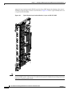
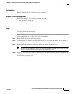
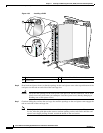
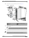
Step 5 Grasp the card carrier handle with one hand and place your other hand under the carrier to support and
guide it into the correct slot. Slide the card halfway into the slot. Avoid touching the card circuitry or
any connectors (see Figure 4-33).