


2-17
Cisco CRS Carrier Routing System 8-Slot Line Card Chassis Installation Guide
OL-6256-17
Chapter 2 Installing and Removing Power Components
How to Install or Remove Fixed Configuration Power Components
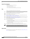
What to Do Next
After performing this task, install the DC PEMs or AC rectifiers (see the “Installing a DC PEM or AC
Rectifier” section on page 2-22).
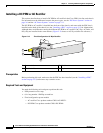
Note After installing a DC PDU, you need to connect the DC input wiring before installing the DC PEMs. For
more information, see the “Installing DC PDU Cables” section on page 2-19.
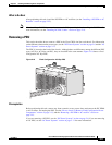
Removing a PDU
This section describes how to remove a PDU in the Cisco CRS 8-slot line card chassis. For information
on the difference between the power types, see the “DC Power Systems” section on page 2-6 and the “AC
Power Systems” section on page 2-11.
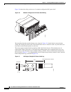
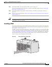
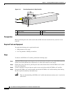
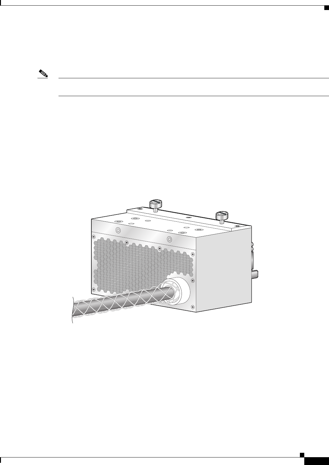
The PDU is located at the back of the chassis. Although there are differences among the different PDU
types (AC Wye, AC Delta, and DC), they are installed in the same manner. Figure 2-10 shows a fixed
configuration AC Wye PDU.
Figure 2-10 Fixed Configuration AC Wye PDU
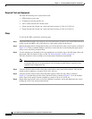
Prerequisites
Before performing this task, remove any front cosmetic covers, power down and remove the DC PEMs
or AC rectifiers, and unplug the PDU. See the “How to Install or Remove Fixed Configuration Power
Components” section on page 2-13, and the “Removing a DC PEM or AC rectifier” section on
page 2-23.
If you are removing a DC PDU, see the “DC Power Systems” section on page 2-6; if you are removing
an AC PDU, see the “AC Power Systems” section on page 2-11 for more information.
122288