


4-54
Cisco CRS Carrier Routing System 8-Slot Line Card Chassis Installation Guide
OL-6256-17
Chapter 4 Installing and Removing Line Cards, PLIMs, and Associated Components
How to Install or Remove a Physical Layer Interface Module
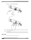
Some PLIMs contain Class 1 lasers, and some contain Class 1M. See the documentation for the specific
PLIM for details.
What to Do Next
After performing this task, replace any front cover plates.
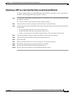
Verifying the Installation of a PLIM
This section describes how to verify that the PLIM has been properly installed.
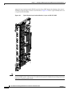
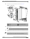
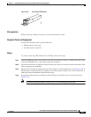
Figure 4-35 shows the PLIM front panel (in this case, a 14-port 10-GE XFP PLIM).
Figure 4-35 PLIM Front Panel Indicators
Troubleshooting the PLIM
If the installed or replaced PLIM fails to operate or to power up on installation:
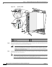
• Make sure that the PLIM is seated firmly in the Cisco CRS 8-slot line card chassis slot. One easy
way to verify physical installation is to see whether the front faceplate of the PLIM is even with the
fronts of the other PLIMs installed in the card cage.
• Check whether the ejector levers are latched and that the captive screws are fastened properly. If you
are uncertain, unlatch the levers, loosen the screws, and attempt to reseat the PLIM.
• Examine the alarm LEDs on the RP to see if there are any active alarm conditions.
• Examine the power shelves to see whether the chassis, as a whole, is receiving power.
Use the status LEDs, located on the PLIM faceplate, to verify the correct installation of the card:
There are two types of LEDs on a PLIM: the board-level LED labeled Status and the port-level LEDs
that are labeled differently depending on the PLIM type. When the PLIM is properly installed, the Status
LED turns green. If this LED is off, verify that the associated MSC, FP, or LSP line card is installed
correctly. For details on the information provided by the port-level LEDs, see the documentation specific
to that PLIM.
1 Port LED (one per port) 2 Status LED
249625
1 2