


3-6
Cisco CRS Carrier Routing System 8-Slot Line Card Chassis Installation Guide
OL-6256-17
Chapter 3 Installing and Removing Air Circulation Components
How to Install or Remove Air Circulation Components
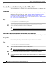
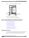
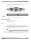
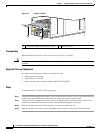
A Cisco CRS 8-slot line card chassis fan tray operates in either the upper or lower fan tray slot. Each fan
tray is installed into the rear (MSC) side of the chassis (see Figure 3-4).
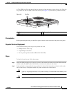
Figure 3-4 Fan Tray
Prerequisites
Before performing this task, you must first remove any front cover plates.
Required Tools and Equipment
You need the following tools to perform this task:
• ESD-preventive wrist strap
• Large flat-blade screwdriver
Steps
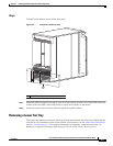
To remove a lower fan tray, follow these steps:
Step 1 Attach the ESD-preventive wrist strap to your wrist and connect its leash to one of the ESD connection
sockets on the rear (MSC) side of the chassis or a bare metal surface on the chassis.
Step 2 Using the screwdriver, loosen the two captive screws on the fan tray.
Caution A fan tray weighs approximately 19.15 pounds (8.69 kg). Use both hands when handling a fan
tray.
Step 3 Rotate the fan tray handle out.
Step 4 Grasp the fan tray handle and pull it straight out to disconnect the fan tray from the connector mounted
on the back of the fan tray. Slide the fan tray halfway from the fan tray bay.
1 Captive screws 3 Fan tray handle
2 Fan tray rail
122289
3
2
1