A-1
Cisco CRS Carrier Routing System 8-Slot Line Card Chassis Installation Guide
OL-6256-17
APPENDIX
A
Cisco CRS Carrier Routing System 8-Slot Line
Card Chassis Specifications
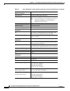
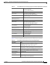
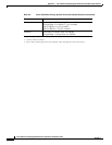
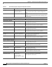
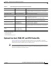
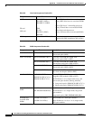
Table A-1 lists the specifications for the Cisco CRS Carrier Routing System 8-Slot Line Card Chassis.
Table A-1 Cisco CRS 8-Slot Line Card Chassis Component and Power Specifications
Supported Cards and Modules
8 modular services cards (MSCs), forwarding processor
(FP) cards, or label switch processor (LSP) cards (line
cards)
8 physical layer interface modules (PLIMs),
one for each MSC, FP, or LSP
4 switch fabric cards (SFCs)
2 route processor (RP) cards or 2 performance route
processor (PRP) cards
2 fan trays
1 air filter
Power Distribution Units, Fixed
Configuration
2 AC or 2 DC power distribution units (PDUs)
(cannot mix AC and DC PDUs in the chassis)
DC PDU Supports 1 DC power entry module (PEM)
AC PDU Supports 1 AC rectifier module
Power Shelves, Modular
Configuration
2 AC or 2 DC power shelves
(cannot mix AC and DC power shelves in the chassis)
DC power shelf Accepts up to 4 DC PMs
AC power shelf Accepts up to 3 AC PMs
Maximum Power Consumption,
Fixed Configuration
This represents total input power.
Maximum DC 8.0 kW (assuming 94% efficiency)
Maximum AC 8.5 kW (Delta or Wye 3-phase) (assuming 88%
efficiency)
Note Proper grounding is also required at the site to
ensure that equipment is not damaged by
lightning or power surges.


