


2-2
Cisco CRS Carrier Routing System 8-Slot Line Card Chassis Installation Guide
OL-6256-17
Chapter 2 Installing and Removing Power Components
Power Component Information Common to Two Types of Power System
This chapter presents the following topics:
• Power Component Information Common to Two Types of Power System, page 2-2
• How to Install or Remove Fixed Configuration Power Components, page 2-13
• How to Install or Remove Modular Configuration Power Components, page 2-25
• Converting a Chassis from Fixed Configuration Power to Modular Configuration Power, page 2-54
Power Component Information Common to Two Types of Power
System
This section contains information shared by the fixed configuration power components and the modular
configuration power components in the following topics:
• Basic Chassis Power Details, page 2-2
• Bonding and Grounding Guidelines, page 2-4
• How to Install the Chassis Ground Cable, page 2-5
• DC Power Systems, page 2-6
• AC Power Systems, page 2-11
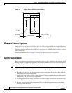
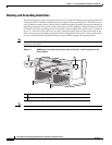
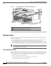
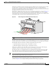
Basic Chassis Power Details
The Cisco CRS 8-slot line card chassis can be configured with either a DC-input power subsystem or an
AC-input power subsystem. The chassis power system provides the necessary power for chassis
components. Site power requirements differ, depending on the source voltage used.
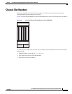
A fixed configuration AC PDU connects to an AC rectifier, while a fixed configuration DC PDU
connects to a DC PEM. A modular configuration AC power shelf houses up to 3 AC PMs, while a
modular configuration DC power shelf houses up to 4 DC PMs. It is required that you use only one type
of power shelf in a chassis at a time.
Note In a modular configuration power system, both AC and DC power supplies are referred to as power
modules (PMs).
Warning
This unit might have more than one power supply connection. All connections must be removed to
de-energize the unit.
Statement 1028