


3-9
Cisco CRS Carrier Routing System 8-Slot Line Card Chassis Installation Guide
OL-6256-17
Chapter 3 Installing and Removing Air Circulation Components
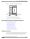
How to Install or Remove Air Circulation Components
Steps
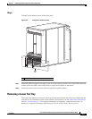
To remove an upper fan tray, follow these steps:
Step 1 Attach the ESD-preventive wrist strap to your wrist and connect its leash to one of the ESD connection
sockets on the rear (MSC) side of the chassis or a bare metal surface on the chassis.
Step 2 Using the screwdriver, unscrew the two captive screws holding the fan tray bay door in place.
Step 3 Lift the door up; you may need a second person to hold it in the open position.
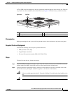
Step 4 Rotate the handle on the fan tray to the open position.
Step 5 Pull firmly and steadily on the fan tray handle to unseat it from the chassis connector, and then slide it
partway from the fan tray bay.
Caution Do not pull too hard on the fan tray; too strong a pull can cause the tray to slide out too quickly,
causing your hand to scrape against the fan tray door.
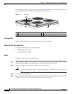
Step 6 Place your hand under the fan tray to support it from beneath.
Caution A fan tray weighs approximately 19.15 pounds (8.69 kg). Use both hands when handling a fan
tray.
Step 7 Slide the fan tray from the bay and set it carefully aside.
Step 8 Replace the fan tray bay door and tighten the two captive screws on the fan tray cover bay door.
What to Do Next
After performing this task, replace the front cover plates.
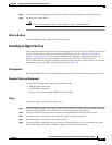
Installing the Chassis Air Filter
This section describes how to install the air filter in the Cisco CRS 8-slot line card chassis. For further
information, see the “About Line Card Chassis Airflow” section on page 3-1. For complete information
on regulatory compliance and safety, see Regulatory Compliance and Safety Information for the Cisco
CRS Carrier Routing System.
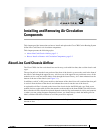
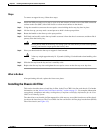
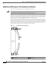
The chassis has a serviceable air filter mounted in a slide-out tray, accessible from the rear of the chassis
just above the lower fan tray. The Cisco CRS 8-slot line card chassis air filter plugs into the front (PLIM)
side of the chassis (see Figure 3-5).