


4-29
Cisco CRS Carrier Routing System 8-Slot Line Card Chassis Installation Guide
OL-6256-17
Chapter 4 Installing and Removing Line Cards, PLIMs, and Associated Components
How to Install or Remove an MSC, FP, or LSP
3. Examine the alarm LEDs on the RP to see if there are any active alarm conditions.
4. Examine the power shelves to see whether the chassis, as a whole, is receiving power.
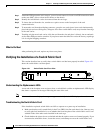
Switch Fabric Card Status LEDs
Use the status LEDs, located on the switch fabric card faceplate, to verify the correct installation of the
card:
• When the card is properly installed, the Status turns green. If this LED is off, verify that the card is
installed correctly.
• When the Status is blinking yellow, a problem exists on the board.
• When the Status is off, the board state is unknown. Verify that there is power to the board by looking
at the indicators on the power module.
• If there is a failure during the board boot sequence, the two-row, four-character alphanumeric
display indicates the current boot phase to assist you in debugging the board failure.
How to Install or Remove an MSC, FP, or LSP
This section contains the following procedures:
• Installing an MSC, FP, or LSP, page 4-29
• Removing an MSC, FP, or LSP, page 4-33
• Verifying the Installation of an MSC, FP, or LSP, page 4-36
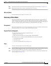
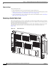
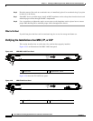
Installing an MSC, FP, or LSP
This section describes how to install an MSC, FP, or LSP line card in the Cisco CRS 8-slot line card
chassis. For more detailed information on the line card , see Cisco CRS Carrier Routing System 8-Slot
Line Card Chassis System Description.
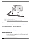
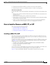
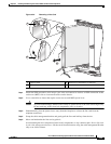
The MSC, FP, and LSP line cards are Layer 3 forwarding engines in the Cisco CRS Series routing system
(see Figure 4-22). A line card can be paired with different types of physical layer interface modules
(PLIMs) to provide a variety of interfaces.
• The MSCs include: CRS-MSC, CRS-MSC-B, CRS-MSC-140G, and CRS-MSC-X (200G).
• The FPs include: CRS-FP-140, CRS-FP-X (200G).
• The LSP is: CRS-LSP.
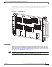
A line card fits into any available MSC slot and connects directly to the midplane. If you install a new
line card, you must first remove the MSC impedance carrier from the available slot.
Figure 4-22 shows the CRS-MSC-140G MSC. The other MSC, FP, and LSP cards are similar.