


CHAPTER
3-1
Cisco CRS Carrier Routing System 8-Slot Line Card Chassis Installation Guide
OL-6256-17
3
Installing and Removing Air Circulation
Components
This chapter provides instructions on how to install and replace the Cisco CRS Carrier Routing System
8-Slot Line Card Chassis air circulation components.
This chapter presents the following topics:
• About Line Card Chassis Airflow, page 3-1
• How to Install or Remove Air Circulation Components, page 3-2
About Line Card Chassis Airflow
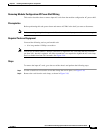
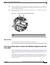
The Cisco CRS 8-slot line card chassis has two fan trays, each with four fans, that cool the chassis card
cages.
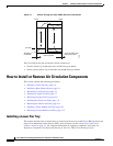
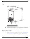
The top fan pulls air into the lower portion of the front of the chassis, up across the cards in the front of
the chassis, and through the upper fan tray. Air flows out of the upper fan tray and down across all the
modular service cards and switch fabric cards through the lower fan tray; air is then exhausted out the
bottom of the rear of the chassis (see Figure 3-1).
In addition, each AC or DC power module at the bottom of the chassis has self-contained fans that pull
in cool air from the front of the chassis and exhaust the warm air out the rear of the chassis.
A replaceable air filter is located on the front of the chassis below the PLIM card cage. Each power
module also has a replaceable air filter that attaches to the module at the front (PLIM) side of the chassis.
How often the air filters should be replaced depends on the facility environment. In a dirty environment,
or when you start getting frequent temperature alarms, you should always check the intake grills for
debris, and then check the air filters to see if they need to be replaced.
Note We recommend that you check the air filters once a month. Replace a filter when you notice a significant
amount of dust.