


4-45
Cisco CRS Carrier Routing System 8-Slot Line Card Chassis Installation Guide
OL-6256-17
Chapter 4 Installing and Removing Line Cards, PLIMs, and Associated Components
How to Install or Remove a PCMCIA Card
3. Examine the alarm LEDs on the to see if there are any active alarm conditions.
4. Examine the power shelves to see whether the chassis, as a whole, is receiving power.
Status LEDs
Use the status LEDs, located on the card faceplate, to verify the correct installation of the card:
• When the card is properly installed, the Status LED turns green. If this LED is off, verify that the
card is installed correctly.
• When the Status LED is blinking yellow, a problem exists on the board.
• When the Status LED is off, the board state is unknown. Verify that there is power to the board by
looking at the indicators on the power module.
• When the Primary LED is on, the board is executing control processing functions and is not in a
secondary or standby role.
• If there is a failure during the board boot sequence, the four-row, four-character alphanumeric
display indicates the current boot phase to assist you in debugging the board failure.
How to Install or Remove a PCMCIA Card
This section contains the following procedures:
• Installing a PCMCIA Card, page 4-45
• Removing an RP PCMCIA Card, page 4-46
Installing a PCMCIA Card
This section describes how to install a PCMCIA card in an RP or a DRP card PCMCIA slot. For more
detailed information on PCMCIA cards, see the “Information About Hard Drives and PCMCIA Cards”
section on page 4-12, or Cisco CRS Carrier Routing System 8-Slot Line Card Chassis System
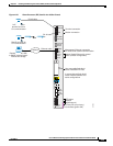
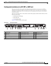
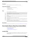
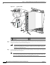
Description. Figure 4-31 shows you the location of the PCMCIA door in the RP card faceplate. (The
PCMCIA cards for the DRP are in a similar location.)
Note Only disk1: can be installed in or removed from the CRS 8-slot line card chassis Route Processor.
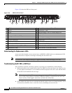
Figure 4-31 RP Card PCMCIA Slot Door
1 PCMCIA flip-up door
122891
1