


4-36
Cisco CRS Carrier Routing System 8-Slot Line Card Chassis Installation Guide
OL-6256-17
Chapter 4 Installing and Removing Line Cards, PLIMs, and Associated Components
How to Install or Remove an MSC, FP, or LSP
Step 6 Place the removed line card on an antistatic mat, or immediately place it in an antistatic bag if you plan
to return it to the factory.
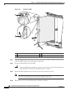
Step 7 If the MSC slot is to remain empty, install an MSC impedance carrier to keep dust from the chassis and
maintain proper airflow through the MSC compartment.
Step 8 Use a screwdriver to tighten the captive screws next to each impedance carrier ejector lever to ensure
proper EMI shielding and to maintain proper airflow throughout the chassis.
What to Do Next
If you did not place the line card in an antistatic bag, do so now for storage and future use.
Verifying the Installation of an MSC, FP, or LSP
This section describes how to verify that a line card has been properly installed.
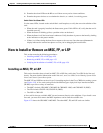
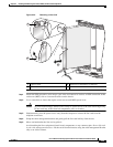
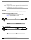
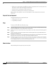
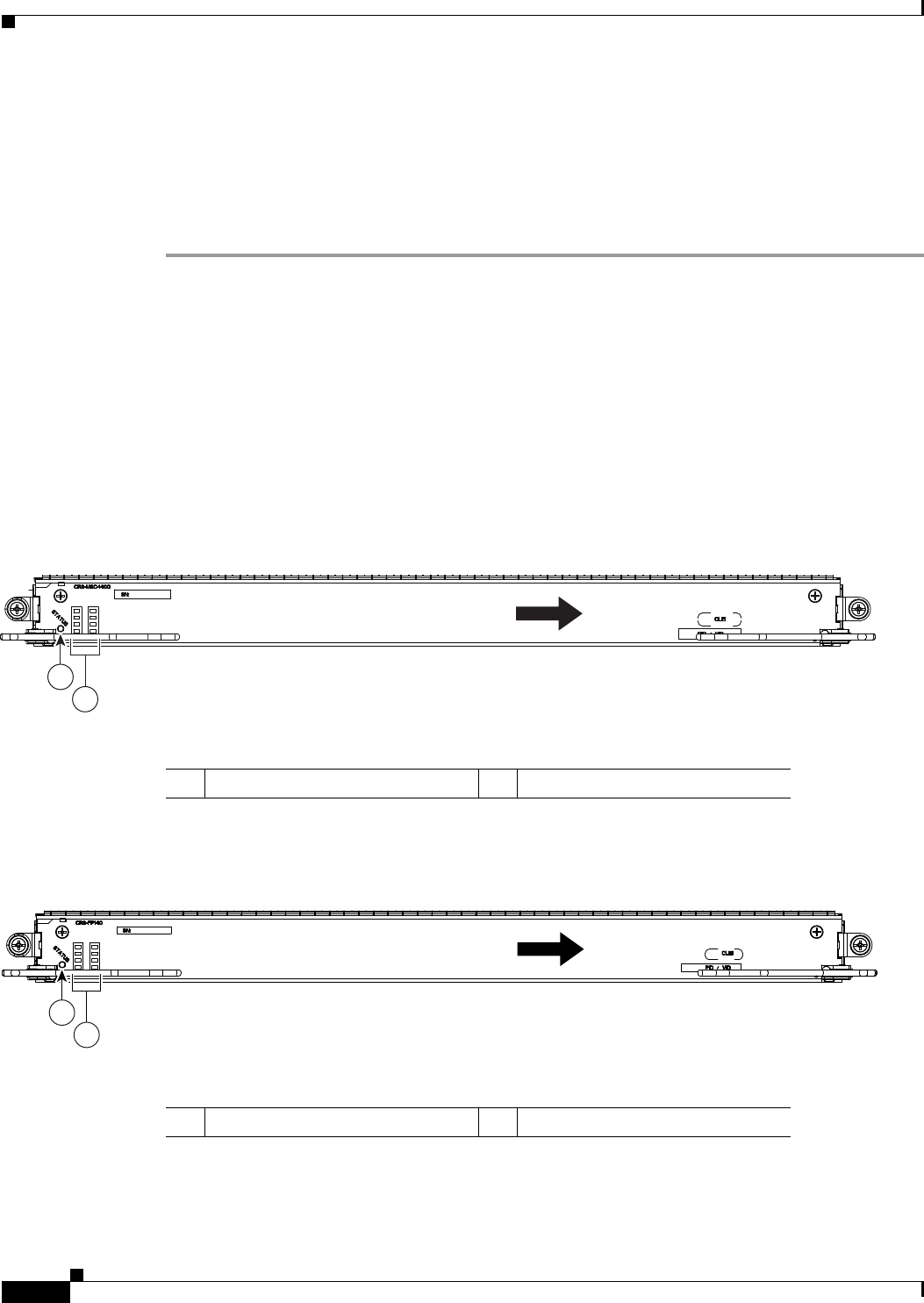
Figure 4-25 is an illustration of the MSC-140G front panel.
Figure 4-25 CRS-MSC-140G Front Panel
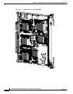
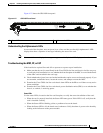
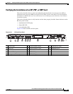
Figure 4-26 shows the FP-140 FP face panel.
Figure 4-26 CRS-FP140 Front Panel
1 Status LED 2 Alphanumeric LEDs
249639
1
2
INSTALL
THIS SIDE
UP
1 Status LED 2 Alphanumeric LEDs
249638
1
2
INSTALL
THIS SIDE
UP