


4-25
Cisco CRS Carrier Routing System 8-Slot Line Card Chassis Installation Guide
OL-6256-17
Chapter 4 Installing and Removing Line Cards, PLIMs, and Associated Components
How to Install or Remove a Switch Fabric Card
Step 3 Visually inspect the connector pins on the card before you insert it into the chassis. Do not attempt to
install a card with bent pins, as this may damage the chassis midplane connectors.
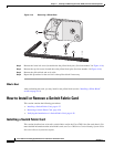
Step 4 Grasp the card carrier handle with one hand and place your other hand under the carrier to support and
guide it into the correct slot.
Step 5 Position the card for insertion into the card cage slot. Avoid touching the card circuitry or any
connectors.
Note Alignment grooves exist on each slot in the card cage. When you install a card in the card cage,
make sure that you align both edges of the card carrier in the slot grooves.
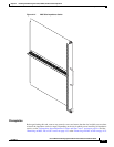
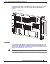
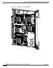
Step 6 Orient the switch fabric card so that the PCB faces left and the carrier is to the right; if the card does not
slide easily into the slot, the orientation may be wrong and the misorientation rejection flange is stopping
the card from going in. Reorient the switch fabric card, if necessary.
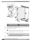
Step 7 Carefully slide the switch fabric card into the slot until the ejector levers meet the edges of the card cage,
then stop when the ejector lever hooks catch the lip of the card cage. If they do not catch, try reinserting
the switch fabric card until the ejector lever hooks are fully latched.
Note The insertion of the switch fabric card into the chassis may require more force than is typical of the other
cards in the chassis.
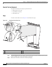
Step 8 Pivot both card ejector levers so that the openings on the card ejector cams at the top and bottom of the
card pass over the tabs on each side of the card cage slot.
Caution Verify that the openings on the card ejector cams pass over the tabs; otherwise, one or both
ejector levers may bind when you attempt to close the levers, thereby damaging or breaking
one or both of them.
Step 9 Continue sliding the card into the card cage slot until the openings on the card ejector cams engage the
tabs on each side of the card cage slot.
Note Switch fabric cards have guide pins that make initial contact with the midplane connector as you
slide a card into its slot. After the guide pins make contact, continue pushing the card carrier
until the card ejector levers begin pivoting forward, toward the handle in the card carrier.
Step 10 To seat the card in the midplane connector, grasp both card ejector levers and pivot them inward toward
the handle in the card carrier until they are flush against the front edge of the card carrier.
Tip The flange on the front panel of the card carrier should be flush against the card cage.
Step 11 Partially tighten the two captive screws on the front panel of the card (either by hand or with the
screwdriver) to make sure that they are both engaged.
Step 12 Use the screwdriver to fully tighten the captive screws to seat the card firmly in the slot.