


2-4
Cisco CRS Carrier Routing System 8-Slot Line Card Chassis Installation Guide
OL-6256-17
Chapter 2 Installing and Removing Power Components
Power Component Information Common to Two Types of Power System
Bonding and Grounding Guidelines
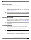
The router chassis has safety earth ground connections in conjunction with the power cabling to the fixed
configuration PDUs. Modular configuration power supports chassis grounding only. The chassis allows
you to connect the central office ground system or interior equipment ground system to the bonding and
grounding receptacles on the router chassis, when either a fixed or modular configuration power system
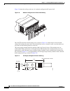
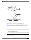
is installed. Six chassis grounding points are provided at the rear (MSC) side of the chassis, as shown in
Figure 2-1. Each side of the chassis has one pair of threaded ground studs located on the inside of the
chassis and two sets of grounding receptacles located on the outside of the chassis. These ground points
are also called the network equipment building system (NEBS) bonding and grounding points.
Note These bonding and grounding receptacles satisfy the Telcordia NEBS requirements for bonding and
grounding connections.
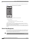
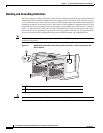
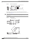
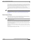
Figure 2-1 NEBS Bonding and Grounding Points (Rear of Chassis) - Fixed Configuration AC
Power Shown
Caution Do not remove the chassis ground cable unless the chassis is being replaced.
1 NEBS bonding and grounding points (inside chassis)
2 NEBS bonding and grounding points (outside chassis)
122792
2
1