


5-5
Cisco CRS Carrier Routing System 8-Slot Line Card Chassis Installation Guide
OL-6256-17
Chapter 5 Installing and Removing Exterior Components
Installing or Removing the Front Side Exterior Components
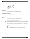
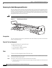
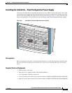
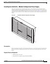
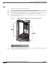
Installing the Inlet Grille—Fixed Configuration Power Supply
This section describes how to install the inlet grille on a Cisco CRS 8-slot line card chassis with a fixed
configuration power supply installed. The inlet grille covers the power module and air intake areas at the
bottom of the front (PLIM) side of the chassis, just below the card cage. Figure 5-3 shows the inlet grille
that can be installed on a Cisco CRS 8-slot line card chassis with a fixed configuration power supply.
Figure 5-3 Inlet Grille—Fixed Configuration Power Supply
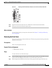
Prerequisites
Before installing the inlet grille, you should mount the chassis in a rack and remove the rear handle pulls.
See Cisco CRS Carrier Routing System 8-Slot Line Card Chassis Unpacking, Moving, and Securing
Guide.
Required Tools and Equipment
• ESD-preventive wrist strap
• Inlet grille (Cisco product number: CRS-8-FRNT-GRILL=)
• 6 in. long number 1 Phillips screwdriver
• Left AC rectifier power handle (Cisco product number: FABMTL,EXTENSION,PWR,L,HQ,HFR)
• Right AC rectifier power handle (Cisco product number: FABMTL,EXTENSION,PWR,R,HQ,HFR)
210878
OT
I/LIM
(AC ONLY)
CB/TRIP
IN/FAIL
FLT
PWR/OK
OT
I/LIM
(A
C
O
N
L
Y
)
CB/TRIP
IN/FAIL
FLT
PW
R/O
K