


2-52
Cisco CRS Carrier Routing System 8-Slot Line Card Chassis Installation Guide
OL-6256-17
Chapter 2 Installing and Removing Power Components
How to Install or Remove Modular Configuration Power Components
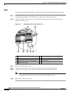
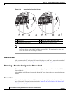
Power Up a Chassis with a Modular Configuration AC or DC Power Shelf
This section describes how to power up a chassis with a modular configuration AC or DC power shelf.
Prerequisites
Before performing this task, you must install the power shelves, wire the power shelves, install the PMs,
and install the route processor (RP) card. See the “Installing a Modular Configuration Power Shelf”
section on page 2-26, the “Installing AC Power Cords or DC Power Shelf Wiring” section on
page 2-35the “Installing AC or DC PMs” section on page 2-40, and the “Installing an RP, PRP, or DRP
Card” section on page 4-38 for more information.
Steps
To power up the chassis, perform the following steps:
Step 1 Turn the facility breaker for both power shelves (Power A and Power B) to the ON position.
Step 2 Turn the power shelf power output breakers to the ON position.
Note There is no required order in which you must turn on the power shelves.
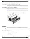
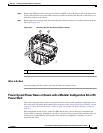
Power Down a Chassis with a Modular Configuration AC or DC Power Shelf
This section describes how to power down a chassis with a modular configuration AC or DC power shelf.
Prerequisites
Before performing this task, you must ensure that the system software has been shut down.
Steps
To power down the chassis, perform the following steps:
Step 1 Turn the power shelf power output breakers to the OFF position.
Note There is no required order in which you must turn off the power shelves.
Step 2 Turn the facility breaker for both power shelves (Power A and Power B) to the OFF position.
Note To power down the chassis entirely, both power shelves must be disconnected to de-energize the chassis
completely.